
Ball type corner lifting device

A lifting device and ball-type technology, applied in the direction of transportation and packaging, conveyors, conveyor objects, etc., can solve problems such as unsatisfactory corners and cumbersome operations

Pending Publication Date: 2020-01-07
东方红光伏科技(乐清)有限公司
View PDF0 Cites 1 Cited by
  • Summary
  • Abstract
  • Description
  • Claims
  • Application Information

AI Technical Summary

Problems solved by technology

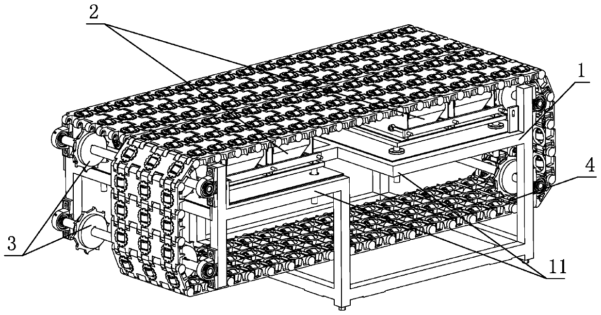
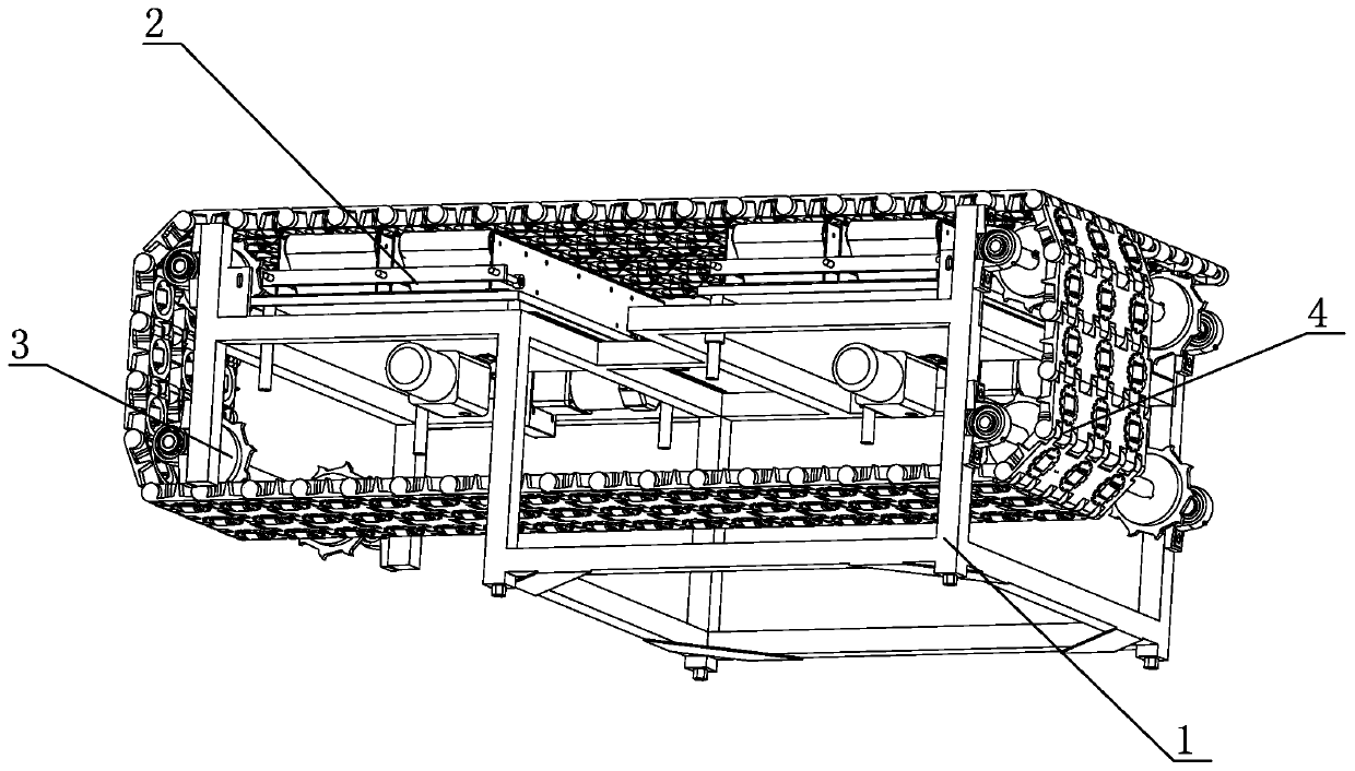
[0006] The beneficial effect of the above structure is that the present invention designs a solution to solve the existing defects that the inspection frame enters the re-inspection conveyor line from the corner of the security inspection conveyor line, and the corner is not ideal or the operation is too cumbersome. The ball-type corner lifting device for the corner problem, wherein the ball-type corner lifting device will be used to drive the conveyor line of the security inspection frame to be spliced ​​by several ball-type mesh belts, and the transmission gears are set on both sides of the installation platform At the same time, the gear teeth of the transmission gear can be meshed with the matching groove on the back of the ball mesh belt, so that the forward or reverse rotation of the transmission gear can be realized, and then the conveyor line can be driven, and the ball type corner lifting device can be realized. When incorporated into the conveyor line used for security inspection and re-inspection, the suspicious and problematic parts are transferred from the security inspection area to the re-inspection area through the forward or reverse rotation of the transmission gear, and the security inspection frame and luggage are sent back to the inspection area after the problem is eliminated. Security inspection area, and when the ball type corner lifting device is used at the security inspection site, in order to ensure that the security inspection frame can enter the area of ​​the ball type corner lifting device, the movement direction of the balls on the ball type mesh belt is set to be related to the present invention. The movement direction of the conveyor line is designed to be vertical, and at the same time, a lifting device is installed below the conveyor line, that is, at the back of the conveyor line. The lifting device mainly involves the transmission belt that controls the rotation of the ball and can be lifted and the motor used to control the lift , when in use, the conveyor line is in normal operation, the lifting device is in a non-working state, that is, the transmission belt does not rise, and when the ball-type corner lifting device needs to be transported to the security inspection area or re-inspection area, the transmission gear of the conveyor line stops Working, synchronous motor action for lifting, so that the transmission belt rotates in the required direction and at the same time the lifting contact with the ball, and then drive the ball to rotate, realize the feed between the ball-type corner lifting device and the security inspection area or re-inspection area, at the same time The ball type corner lifting device has reasonable design, simple structure, convenient operation and easy realization.

Method used


Image

  • Ball type corner lifting device
  • Ball type corner lifting device
  • Ball type corner lifting device

Examples


Embodiment Construction

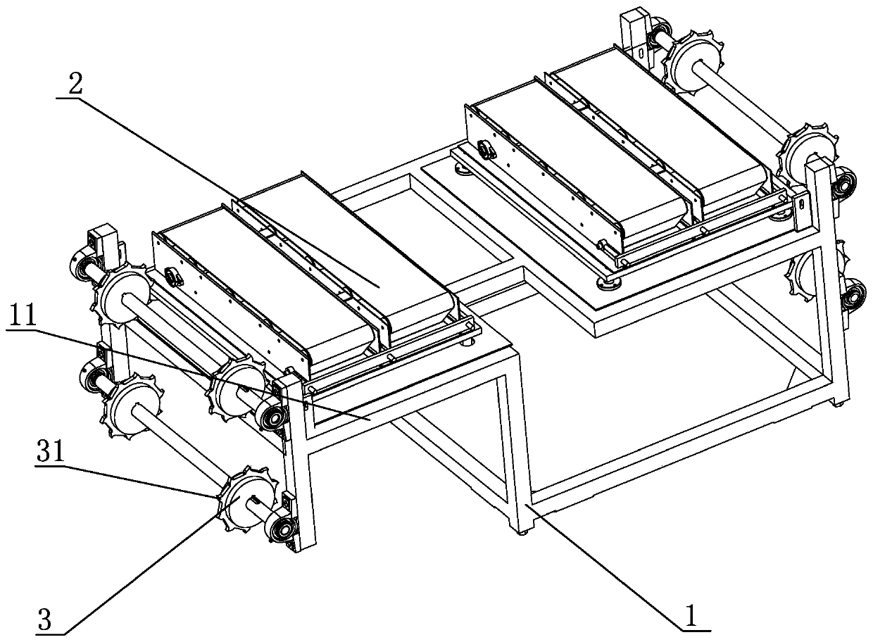
[0020] Such as Figure 1-8 As shown, the specific embodiment of the present invention adopts a ball type corner lifting device, which mainly includes an installation platform 1, a conveying line 4, a lifting device 2 and a transmission gear 3, and the transmission gear 3 is distributed on both sides of the installation platform 1, and the transmission line 4 is distributed on the installation platform 1 in a ring shape, and the transmission gear 3 distributed on both sides of the installation platform 1 is located inside the conveyor line 4. The conveyor line 4 is spliced ​​by several ball-type mesh belts 5, and the ball-type mesh belt 5 It includes a matching groove 57 distributed on the back of the ball-type mesh belt 5 and a ball 51 on the upper limit of the ball-type mesh belt 5. The matching groove 57 is adapted to the gear teeth 31 of the transmission gear 3, and through the matching groove 57 and the gear teeth The meshing of 31 forms the movement of the conveying line ...


PUM


Abstract

The invention provides a ball type corner lifting device. The device comprises a mounting platform, a conveying line, lifting devices and transmission gears, wherein the transmission gears are distributed on the two sides of the mounting platform, the conveying line is annularly distributed on the mounting platform, the transmission gears distributed on the two sides of the mounting platform are located on the inner side of the conveying line, the conveying line is formed by splicing a plurality of ball type mesh belts, the ball type mesh belts comprise matching grooves and balls, movement ofthe conveyor line is realized by engagement of the matching grooves with gear teeth, the movement direction of the conveying line is perpendicular to the rotating direction of the balls, the lifting devices are distributed on the back surface of the ball type mesh belts, and the balls make contact with a transmission belt on the lifting device to realize rotating of the balls, the transmission gears and the conveying line are used in cooperation to realize feeding between a security check area and a re-check area, and the balls are used in cooperation with the transmission belt to realize feeding between the ball type corner lifting device and the security check area or the re-check area, so that the design is reasonable in structure, operation is convenient and the device is convenient torealize.

Description

technical field [0001] The invention relates to security inspection equipment, in particular to a ball-type corner lifting device. Background technique [0002] When the airport conducts security checks on carry-on luggage, the luggage is placed in the security check box, and the luggage is transported to the security inspection machine through the transmission belt for security check. Generally, after passing the security check machine, the luggage that is undoubtedly deemed safe is sent to Baggage claim area. When passing through the security check machine, if suspicious or problematic luggage is found, the staff will manually take out the luggage. After manual troubleshooting, the luggage that is considered safe or basically no problem will be put back manually. In the area to be inspected, re-inspect the suspicious or problematic items found above. If there is no doubt after the re-inspection, the luggage will be transferred to the frame removal area according to the nor...

Claims


Application Information

Patent Timeline
Patent Type & Authority Applications(China)
IPC IPC(8): B65G47/52B65G15/30B65G21/12B65G23/06
CPCB65G47/52B65G15/30B65G21/12B65G23/06
Inventor 刘奇
Owner 东方红光伏科技(乐清)有限公司
Learn More