
Yarn feeding device and method for operating same

A yarn feeding and equipment technology, applied in the field of yarn feeding equipment, can solve the problem of time-consuming assembly

Active Publication Date: 2020-01-07
MEMMINGER IRO GMBH
View PDF10 Cites 0 Cited by
  • Summary
  • Abstract
  • Description
  • Claims
  • Application Information

AI Technical Summary

Problems solved by technology

This scheme and the subsequent assembly are very time consuming

Method used


Image

  • Yarn feeding device and method for operating same
  • Yarn feeding device and method for operating same
  • Yarn feeding device and method for operating same

Examples


Embodiment Construction

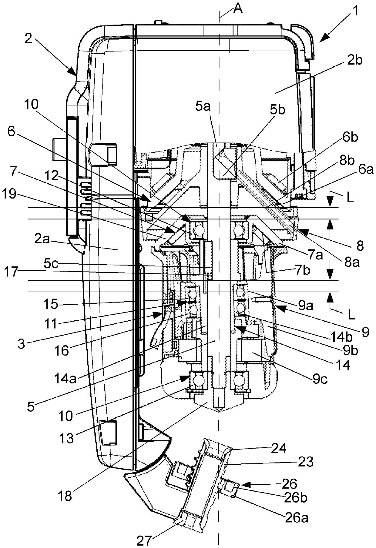
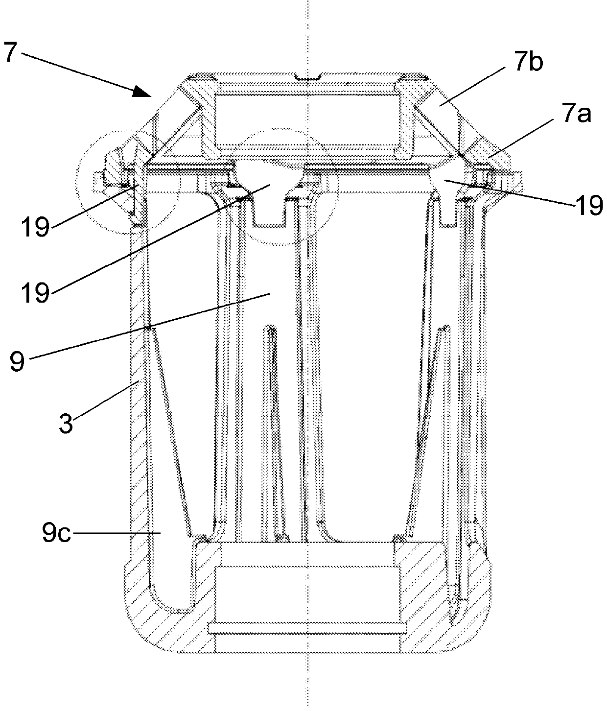
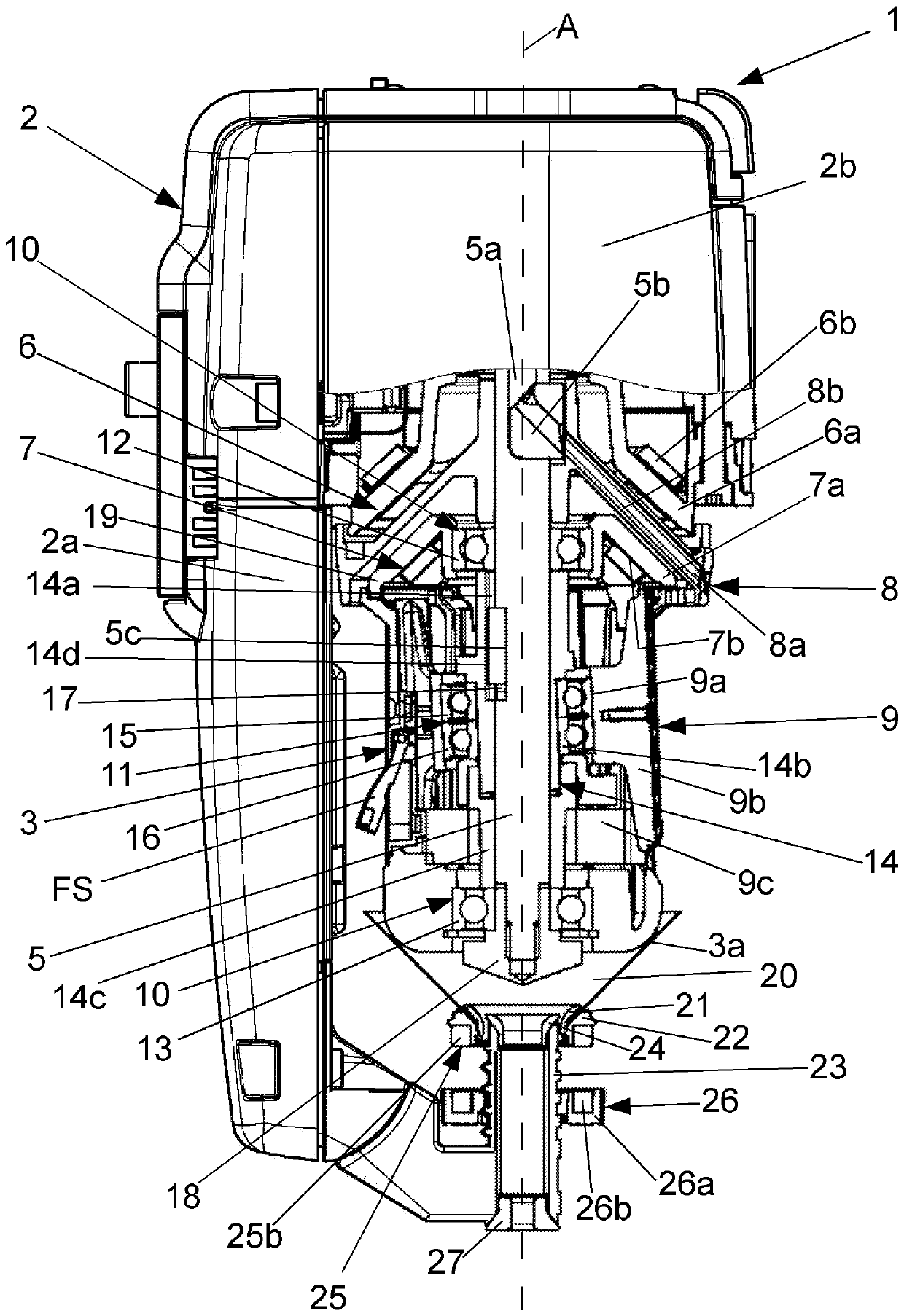
[0056] figure 1 The yarn feeding device 1 shown in is designed as a storage yarn feeding device for feeding yarn 40 to a textile machine. The yarn feeding device 1 has a housing 2 and a storage device with a storage body 3 from which a yarn 40 is withdrawn by the textile machine. The textile machine is, for example, a circular knitting machine.

[0057] The housing 2 includes a bracket 2a and a drive housing 2b. The support 2a is provided with fastening means for fastening the yarn feeding device 1 to a textile machine, for example to a machine ring of a circular knitting machine. In one embodiment, the fastening device is arranged on the side opposite the support 2a. This is indicated by arrow 4a. In this embodiment, the housing comprises a contact plate 2c.

[0058] In a further embodiment, the fastening device is arranged on one side of the carrier 2a instead of the contact plate 2c. This is indicated by arrow 4b.

[0059] The yarn feeding device 1 has a drivable sha...


PUM


Abstract

A yarn feeding device for feeding a yarn to a textile machine according to the present invention is provided with: a housing; a storage device from which the yarn is drawn out through the textile machine; a winding element for winding the yarn onto the storage device; a drivable shaft for driving the winding element; a magnet assembly used for fixing the storage device on the housing; a support mechanism for rotatably supporting the shaft with respect to the storage device; and a locking device used for locking the support mechanism. The winding element is configured to be rotatable with the shaft and disposed between a first magnet unit on the housing and a second magnet unit on the storage device of the magnet assembly. In order to carry out cleaning, a unit is movably formed on the shaft along a cleaning path, the unit comprises the storage device, the second magnet unit and the support mechanism, and the unit can be moved by releasing a locking element.

Description

technical field [0001] The invention relates to a yarn feeding device and a method for feeding yarn to a textile machine. [0002] The yarn feeding device has a housing and a storage device (Speichervorrichtung), from which the yarn is drawn by the textile machine. Such yarn feeding devices are also called storage yarn feeding devices. Background technique [0003] In DE-AS 15 35 641 a storage yarn feeding device known as a weft-intermediate store is described. The yarn feeding device comprises a storage device called a storage body, a shaft, on which the storage body is supported in a fliegend manner, and a winding element, which is said to have a weft yarn The rotating body that feeds the elements. The storage body is secured against rotation. In order to reduce fly, fluff or ash deposits in the region of the storage body, the rotating body is designed in the manner of a fan wheel. [0004] A device for storing yarn-shaped material is known from DE-U 79 02 821, which ...

Claims


Application Information

Patent Timeline
Patent Type & Authority Applications(China)
IPC IPC(8): D04B15/48D04B27/10
CPCD04B15/48D04B15/482D04B27/10D03D47/361D04B15/484D04B15/486
Inventor S.德尔R.考夫曼F.沙尔
Owner MEMMINGER IRO GMBH
Learn More