Display device and driving compensation method thereof

A display device and display panel technology, which is applied to static indicators, instruments, etc., can solve the problems of larger drive circuit chips and unfavorable narrow borders of display devices, etc.

Active Publication Date: 2021-09-14
KUSN INFOVISION OPTOELECTRONICS
View PDF5 Cites 0 Cited by
  • Summary
  • Abstract
  • Description
  • Claims
  • Application Information

AI Technical Summary

Problems solved by technology

However, the above method will lead to larger size of the driving circuit chip, which is not conducive to the narrow frame of the display device.

Method used


Image

  • Display device and driving compensation method thereof
  • Display device and driving compensation method thereof
  • Display device and driving compensation method thereof

Examples


Embodiment Construction

[0024] Various embodiments of the invention will be described in more detail below with reference to the accompanying drawings. In the various drawings, the same elements are denoted by the same or similar reference numerals. For the sake of clarity, various parts in the drawings have not been drawn to scale.

[0025] The specific implementation manners of the present invention will be further described in detail below in conjunction with the accompanying drawings and embodiments.

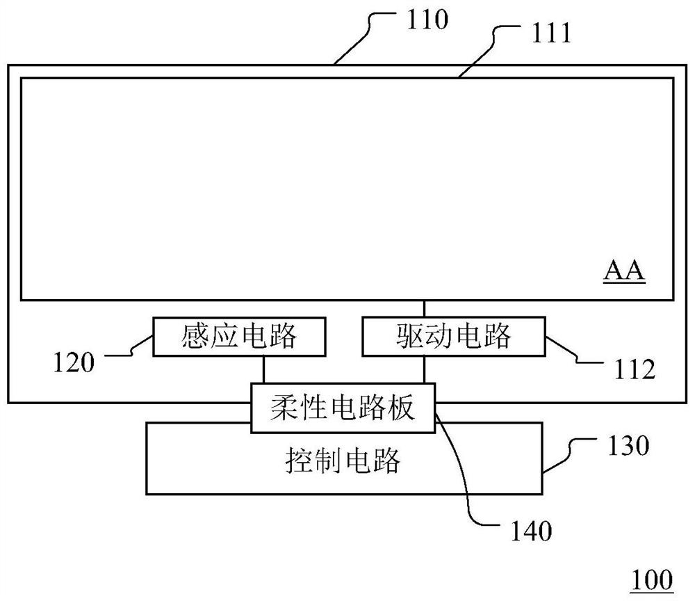
[0026] figure 1 A schematic structural diagram of a display device provided according to an embodiment of the present invention is shown, as shown in figure 1 As shown, the display device 100 includes a display panel 110 , a driving circuit 112 , a sensing circuit 120 , and a control circuit 130 located outside the display panel and connected to the internal circuit of the display panel 110 through a flexible circuit board 140 . The display device 100 may be a liquid crystal display device or an...


PUM


Abstract

The present application discloses a display device and a driving compensation method thereof. The display device includes a display panel; a driving circuit, which provides a driving signal to drive a pixel array in the display panel; a sensing circuit, which is sensitive to temperature and / or light intensity, and the sensing circuit includes an input end; output end; at least one inductive element, connected between the input end and the output end, the equivalent resistance of at least one inductive element changes with the change of temperature and / or light intensity; bias element, connected with the output end, at least The equivalent resistance of a sensing element and the equivalent resistance of the biasing element divide the input voltage to obtain a detection voltage; the control circuit is connected with the sensing circuit to receive the detection voltage, and adjusts the driving signal according to the detection voltage. The present application ensures the display quality of the display device by providing an induction circuit in the display panel to detect the temperature and / or light intensity of the display panel, and setting a control circuit to adjust and obtain a driving signal corresponding to the temperature or light intensity.

Description

technical field [0001] The invention relates to the field of display technology, in particular to a display device and a driving compensation method thereof. Background technique [0002] With the development of display technology, narrower borders of display panels are becoming more and more common. [0003] Whether it is a liquid crystal display device or an organic light-emitting diode display device, thin-film transistors are important components. When the temperature of the display panel decreases, the electron mobility of the thin-film transistor becomes lower, resulting in deterioration of the charging characteristics of the thin-film transistor. At this time If the driving circuit in the display device still provides the same driving signal to the display panel, the display quality of the display panel will be degraded. Moreover, the compatibility of the liquid crystal or the organic light-emitting diode to the same driving signal will also become poor with changes ...

Claims


Application Information

Patent Timeline
Patent Type & Authority Patents(China)
IPC IPC(8): G09G3/3225G09G3/36
CPCG09G3/3225G09G3/3648G09G3/3696
Inventor 郭文豪房耸王鲁杰刘建玮
Owner KUSN INFOVISION OPTOELECTRONICS
Why Eureka
Try Eureka