Triangular expansion type electrical wire holder

一种电气接线、接线座的技术,应用在电气元件、导电连接、电路等方向,能够解决增加接线座接线操作难度等问题,达到减少施工隐患、减小操作难度的效果

Inactive Publication Date: 2020-01-07
LIANG PING
View PDF4 Cites 1 Cited by
  • Summary
  • Abstract
  • Description
  • Claims
  • Application Information

AI Technical Summary

Problems solved by technology

If the space in the direction of force is limited, it will increase the difficulty of wiring the terminal block

Method used


Image

  • Triangular expansion type electrical wire holder
  • Triangular expansion type electrical wire holder
  • Triangular expansion type electrical wire holder

Examples


Embodiment 1

[0011] Embodiment 1: An assembly example of the terminal block 1 .

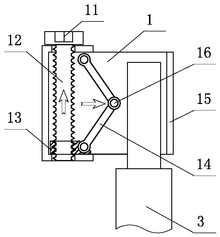
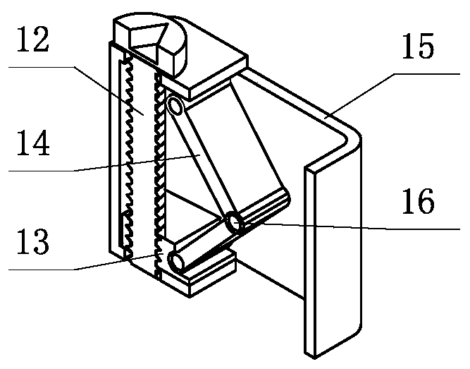
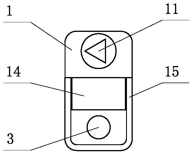
[0012] The shell 15 of terminal block 1 is divided into two areas, one is the installation area of ​​the driving mechanism, this area is closed up and down, and the screw rod 12 that penetrates up and down is installed, and on the upper end of the screw rod 12 and outside the shell 15, there is a screw rod 12 connected as The integrated force applying screw 11 is equipped with an active nut 13 matched with the threads of the screw rod 12 at the bottom of the screw rod 12 and inside the casing 15 . The active nut 13 rises or falls according to the force of the thread along with the forward or reverse rotation of the screw rod 12 . With active nut 13, terminal block 1 shell 15 tops near screw rod 12 positions as two hinge points, two connecting rods 14 are installed, and the other end of connecting rod is hinged with interlocking shaft 16. The other is the wiring area, where the wires 3 to be connected penetra...

Embodiment 2

[0013] Embodiment 2: Wires are inserted into the wiring area of ​​the terminal block 1 from the bottom surface or the front surface.

[0014] From the bottom or front of the terminal block 1, penetrate the part of the wire 3 to be connected with the insulation layer removed into the wiring area, use a special tool to turn the force screw 11 from the positive direction, and drive the screw 12 to rotate forward together, so that the active screw 12 matched at the bottom of the screw 12 The nut 13 rises, and the hinged linkage shaft 16 of the two connecting rods 14 squeezes to the inserted electric wire 3, and the electric wire 3 is tightly clamped between the shell 15 and the linkage shaft 16, and the installation and installation of the electric wire 3 is completed. Connect the conduction function.

Embodiment 3

[0015] Embodiment 3: Press the wires into the wiring area of ​​the terminal block 1 from the side.

[0016] This embodiment is aimed at the terminal block 1 with the side opening 2 of the housing 15 .

[0017] From the side opening 2 of the casing 15, the part of the wire 3 to be connected without the insulation layer is penetrated into the wiring area, and the force applying screw 11 is rotated from the positive direction with a special tool to drive the screw rod 12 to rotate forward together, so that the screw rod 12 matched at the bottom of the screw rod 12 is rotated forward. The active nut 13 rises, and the hinged linkage shaft 16 of the two connecting rods 14 is pressed against the inserted wire 3, and the wire 3 is tightly clamped between the shell 15 and the linkage shaft 16, and the installation of the wire 3 is completed. and connected conduction function.


PUM


Abstract

The utility model relates to a triangular expansion type electric wire holder. The force application part of the wire holder is changed from the vertical direction of a wire into a direction the sameas a direction in which the wire penetrates into the wire holder. The wire holder is mainly composed of a wire holder shell, a screw rod, a driving nut, connecting rods and a linkage shaft. When the screw rod is rotated in a forward direction, the driving nut matched with the bottom of the screw rod rises according to a meshing force between screw threads; the hinged linkage shaft portion of the two connecting rods extrude towards a wiring area, so that the wire is clamped between the shell and the linkage shaft; and the functions of the installation, connection and conduction of the wire arecompleted. The above can be operations can be performed inversely, so that the clamped wire can be relieved. In the whole operation of connecting the wire into the wire holder, the clamping or unclamping action of the mechanism in the wire holder on the wire is completed in the wire holder, so that the appearance size of the wire holder is not changed.

Description

technical field [0001] The invention relates to an accessory for electric connection, in particular to a terminal block for connection between switches, sockets and electric wires. Background technique [0002] In the traditional terminal block, after the wires are inserted into the wiring area of ​​the terminal block, force is applied from a direction perpendicular to the wires, so that the clamping screws or splints continue to occupy the space of the wiring area, clamping the wires penetrating into the wiring area, making it reliable. The connection is on. If the space in the direction of the force is limited, it will increase the difficulty of wiring the terminal block. Contents of the invention [0003] Purpose of the invention: change the force-applying part of the terminal block from the vertical direction of the electric wire to the same direction as the electric wire. That is, after the wires penetrate into the wiring area of ​​the terminal block, the force appl...

Claims


Application Information

Patent Timeline
Patent Type & Authority Applications(China)
IPC IPC(8): H01R4/42H01R9/00H01R9/22
CPCH01R4/42H01R9/00H01R9/22
Inventor 不公告发明人
Owner LIANG PING
Why Eureka
Try Eureka