Linear machining runner for location and transplanting

A technology for positioning transplanting and runners, applied in metal processing equipment, manufacturing tools, assembly machines, etc., can solve the problems of difficulty in maintenance and debugging, efficiency stability, backward control, low efficiency, etc., and achieve the effect of accurate product position.

Pending Publication Date: 2020-01-10
SUZHOU E CONN TECH
View PDF0 Cites 4 Cited by
  • Summary
  • Abstract
  • Description
  • Claims
  • Application Information

AI Technical Summary

Problems solved by technology

[0002] Power socket DC JACK products are now used more and more widely, and the amount of use is increasing, and the required production capacity and quality are also getting higher and higher. In this case, the company is vigorously developing automation equipment to meet the demand and reduce labor costs. The original low-efficiency manual and jig assembly production was upgraded to a generation of automatic machine assembly, which improved the original production capacity, but the efficiency, stability and control of the equipment have fallen behind with the development of the company. The pin insertion mechanism of the previous generation of automatic equipment has relatively strict requirements on materials, lack of stability, and difficulty in maintenance and debugging. Now the company further upgrades the equipment used

Method used


Image

  • Linear machining runner for location and transplanting
  • Linear machining runner for location and transplanting
  • Linear machining runner for location and transplanting

Examples


Embodiment Construction

[0021] The preferred embodiments of the present invention will be described in detail below in conjunction with the accompanying drawings, so that the advantages and features of the invention can be more easily understood by those skilled in the art, so as to define the protection scope of the present invention more clearly.

[0022] see Figure 1 to Figure 8 , the embodiment of the present invention includes:

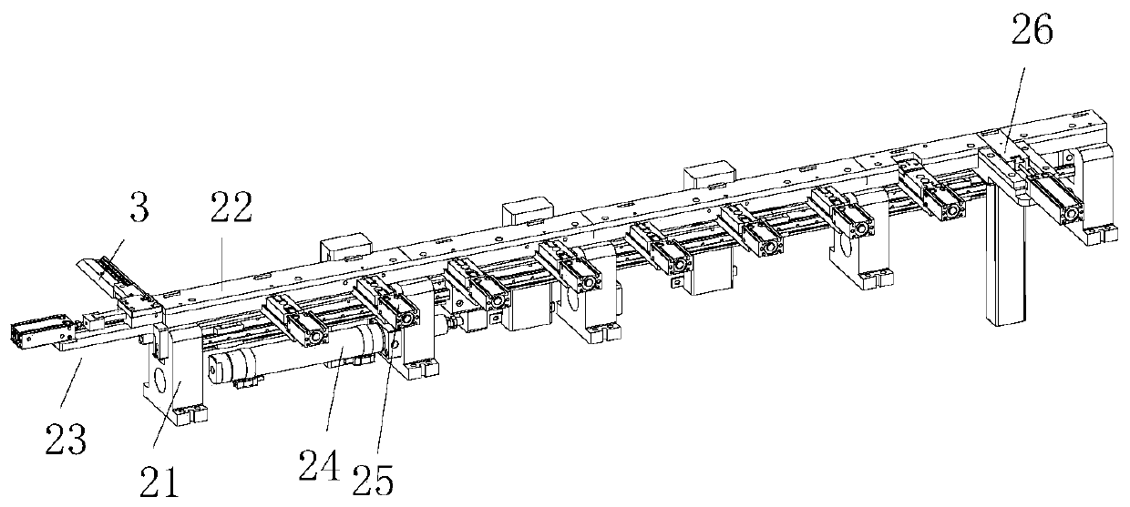
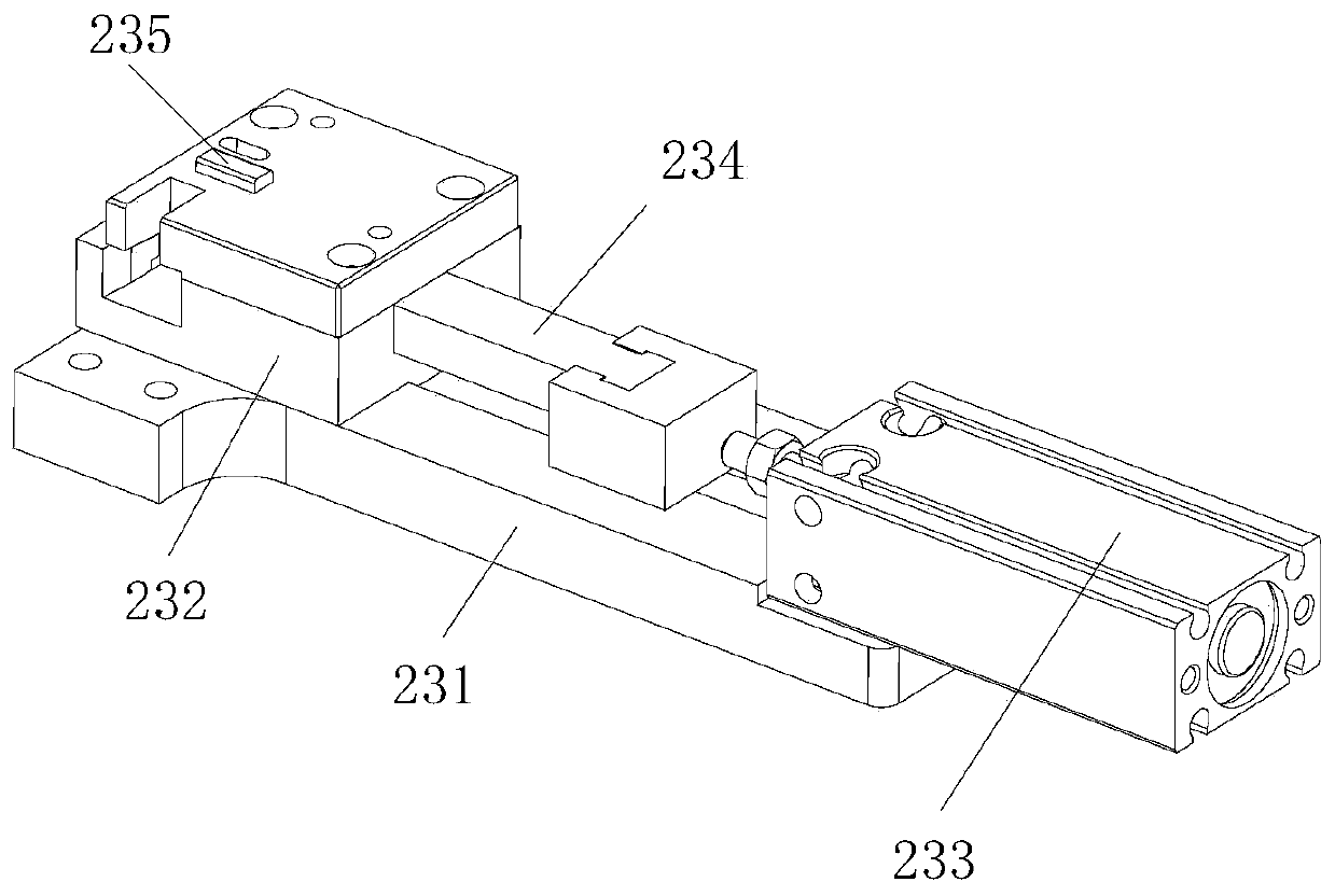
[0023] A linear processing channel for positioning transplanting, the linear processing channel for positioning transplanting includes a support frame 21, a rubber core channel 22, a dislocation feeding component 23, a transplanting device 24, a positioning device 25 and a front-end defective recovery component 26, the The upper end of the support frame 21 is provided with a rubber core flow channel 22, and the feed port of the rubber core flow channel 22 is connected with a direct vibration feeding device. There is a transplanting device 24 , a positioning device 25 ...


PUM


Abstract

The invention discloses a linear machining runner for location and transplanting. The linear machining runner for location and transplanting comprises a support frame, a rubber core runner, a staggered feeding assembly, a transplanting device, location devices and a front-end defective product recovery assembly, wherein the rubber core runner is formed in the upper end of the support frame; a straight-vibration loader is arranged at a charge port of the rubber core runner in a butting manner; the staggered feeding assembly is arranged at the left side of the rubber core runner; the transplanting device is arranged below the rubber core runner; the location devices are equidistantly arranged at the upper end of the rubber core runner; and the front-end defective product recovery assembly isarranged at the right side of the rubber core runner. Through the manner, due to the arrangement for the staggered feeding assembly, blocking for the next product to be loaded in time during loadingcan be ensured; products on a whole rail can be transplanted, and all the products can be uniformly located, so that the accurate positions of the products at each workstation after the transplantingare ensured; and defective products at a front end can be discharged, so that waste for materials in a rear section is avoided.

Description

technical field [0001] The invention relates to the technical field of industrial machinery, in particular to a linear processing channel for positioning transplanting. Background technique [0002] Power socket DC JACK products are now used more and more widely, and the amount of use is increasing, and the required production capacity and quality are also getting higher and higher. In this case, the company is vigorously developing automation equipment to meet the demand and reduce labor costs. The original low-efficiency manual and jig assembly production was upgraded to a generation of automatic machine assembly, which improved the original production capacity, but the efficiency, stability and control of the equipment have fallen behind with the development of the company. The pin insertion mechanism of the previous generation of automatic equipment has strict requirements on materials, lacks stability, and is difficult to maintain and debug. Now the company further upgr...

Claims


Application Information

Patent Timeline
Patent Type & Authority Applications(China)
IPC IPC(8): B07C5/344B07C5/02B23P21/00
CPCB07C5/02B07C5/344B23P21/00
Inventor 王发帅
Owner SUZHOU E CONN TECH
Why Eureka
Try Eureka