Planar screw synchronizer

A synchronizer and screw technology, which is applied in the field of mechanical assembly tooling, can solve the problems of scratches, bumps, and low efficiency of parts, and achieve the effects of avoiding scratches and bumps, liberating manpower, and avoiding collisions and scratches

Inactive Publication Date: 2020-01-10
GUIZHOU HONGLIN MACHINERY
View PDF17 Cites 1 Cited by
  • Summary
  • Abstract
  • Description
  • Claims
  • Application Information

AI Technical Summary

Problems solved by technology

It is easy to cause scratches and bumps on parts during disassembly, and there is a problem of low efficiency during assembly

Method used


Image

  • Planar screw synchronizer
  • Planar screw synchronizer
  • Planar screw synchronizer

Examples


Embodiment Construction

[0028] The present invention will be further described below in conjunction with the accompanying drawings and embodiments, but not as a basis for limiting the present invention.

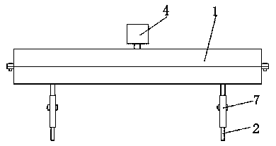
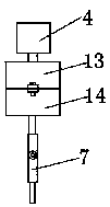
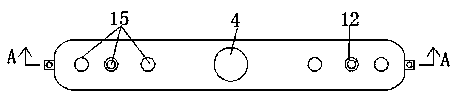
[0029] Example. A planar screw synchronizer, constituted as Figure 1-7 As shown, a housing 1 is included, and a driving assembly is arranged in the housing 1, and the driving assembly connects two driven assemblies; the driven assembly includes a screwdriver head 2 . The drive assembly can drive the screwdriver bits 2 of the two driven assemblies to rotate simultaneously and in the same direction, so as to realize the assembly or disassembly of the two screws on the end cover.

[0030] The driving assembly includes a driving pulley 3 connected to the motor 4 ; the driven assembly includes a driven pulley 5 connected to the driving pulley 3 through a belt 6 . After the motor 4 is started, the driving pulley 3 is driven to rotate, and the driving pulley 3 drives two driven pulleys 5 to rotate throu...


PUM


Abstract

The invention discloses a planar screw synchronizer comprising a shell. A drive assembly is arranged in the shell. The drive assembly is connected with two driven assemblies. Each driven assembly comprises a screwdriver bit. The planar screw synchronizer has the advantages that scratches and collisions can be avoided during part assembling or disassembling, and the work efficiency is high; the planar screw synchronizer is suitable for working conditions of screws at different distances, screws of different types and end covers in different shapes, and the application range is wide.

Description

technical field [0001] The invention relates to the technical field of mechanical assembly tooling, in particular to a planar screw synchronizer. Background technique [0002] Currently, in some products, the end cover and the housing are connected by multiple pairs of screws, and a spring is arranged between the end cover and the housing. In general, when removing the end cover, loosen the screws on one side first, and the end cover will tilt to the other side due to the action of the spring. Then loosen the screws on the other side. After the spring force is balanced, it will collide with the shell due to the unloading force of the side where the end cover is loosened first. Under normal circumstances, the roughness requirements of the end faces of the end caps and shells of these products will be very high, and some even have flat apron grooves. Therefore, if the screws on both sides of the end cover are not loosened at the same time, there will be a risk of damaging th...

Claims


Application Information

Patent Timeline
Patent Type & Authority Applications(China)
IPC IPC(8): B23P19/06
CPCB23P19/06
Inventor 徐旻熹魏艳君黄富城
Owner GUIZHOU HONGLIN MACHINERY
Why Eureka
Try Eureka