Spindle yarn-storing driving device of multifunctional extra-large-stroke yarn storage device

A technology of driving device and yarn storage device, which is applied in the direction of braided fabrics, textiles, and papermaking. It can solve the problems of short spindle strokes and inability to meet the needs of weaving, and achieve the effects of precise transmission, low cost, and long life.

Pending Publication Date: 2020-01-10
XUZHOU HENGHUI BRAIDING MACHINE
View PDF1 Cites 0 Cited by
  • Summary
  • Abstract
  • Description
  • Claims
  • Application Information

AI Technical Summary

Problems solved by technology

[0005] The purpose of the present invention is to provide a multi-functional super large stroke yarn storage and release spindle spindle yarn storage driving device to solve the problem that the spindle stroke of the existing knitting machine is short, sometimes loose and sometimes tight, and cannot meet the needs of weaving

Method used


Image

  • Spindle yarn-storing driving device of multifunctional extra-large-stroke yarn storage device
  • Spindle yarn-storing driving device of multifunctional extra-large-stroke yarn storage device
  • Spindle yarn-storing driving device of multifunctional extra-large-stroke yarn storage device

Examples


Embodiment 1

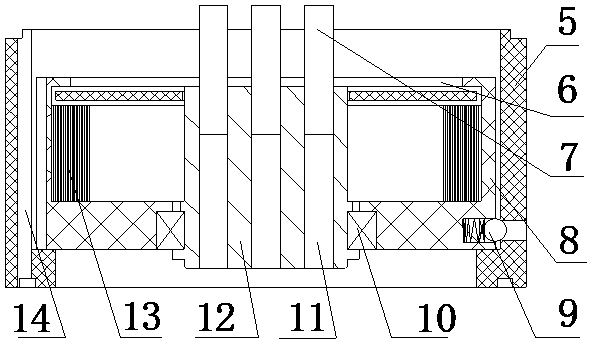
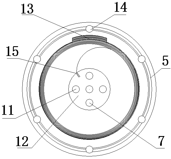
[0025] Embodiment 1: The spindle yarn storage driving device includes: a fixed sleeve 5, a dial shaft 7, a driver seat 8, a driver 13, a rotor shaft 12, a shaft hole 11, a driver bearing 10, a shaft cover 6, a transition hole 14, a fixed Groove 15 and positioning connector 9;

[0026] The driver seat 8 is fixedly connected in the fixed sleeve 5 through the positioning connector 9; there is a transition hole 14 through the fixed sleeve 5; a driver 13 is connected in the driver seat 8, and one end of the driver 13 is embedded in the driver seat 8. In the groove, the other end of the driver 13 is stuck on the fixed groove 15 of the rotor shaft 12; the rotor shaft 12 is connected to the axis center position of the driver seat 8 through the driver bearing 10; there is a dial shaft hole 11 on the rotor shaft 12, and the dial shaft 7 is connected to On the dial shaft hole 11 , the dial shaft 7 passes through the dial shaft cover 6 .

[0027] The driver seat 8 is cylindrical, one end...

Embodiment 2

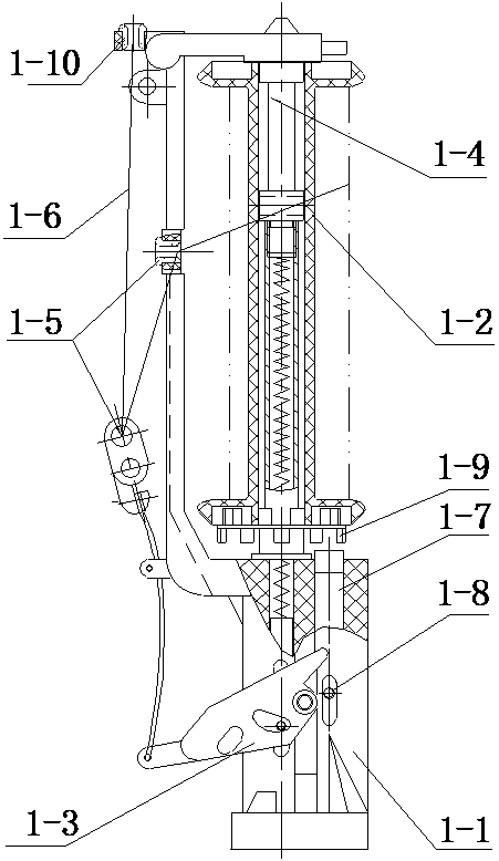
[0031] Embodiment 2: There are four retractable and storage yarn drive devices; the four retractable and storage yarn drive devices are fixed in series by bolts; the first drive device 1, the second drive device 2, the third drive device 3 and the first drive device The four driving devices 4 are sequentially connected in series by bolts from top to bottom.

[0032] The dial shaft 7 protruding from the top of the retractable yarn storage drive device below is inserted into the dial shaft hole 11 at the bottom of the upper retractable yarn storage drive device.

[0033] The uppermost retractable yarn storage driving device dial shaft 7 is inserted into the positioning hole on the lower end surface of the yarn storage device shaft of the constant tension pay-off device.

[0034] The rotation of the rotor shaft 12 of the retractable yarn storage drive device drives the yarn storage device shaft to rotate simultaneously through the dial shaft; in this embodiment, four retractable ...


PUM


Abstract

The invention belongs to two-dimensional and three-dimensional knitting machine yarn storage devices, and relates to a spindle yarn-storing driving device of a multifunctional extra-large-stroke yarnstorage device. A driver seat is fixedly connected in each fixing sleeve through a positioning connector; a transition hole penetrating top and bottom of each fixing sleeve is formed in the same; a driver is connected in each driver seat, one end of each driver is inlaid in a groove of the corresponding driver seat, and the other end of each driver is clamped on a fixing groove of a rotor shaft; each rotor shaft is connected to the axial position of the corresponding driver seat through a driver bearing; a shifting shaft hole is formed in each rotor shaft, a shifting shaft is connected to theshifting shaft hole, and the shifting shaft penetrates a corresponding shifting shaft sealing cover. The spindle yarn-storing driving device has the advantages that a plurality of drivers are connected in series, the first driver starts to twist under the action of the rotating force of the yarn storage device, the second driver starts to twist when the force reaches the rated limit, and the restis carried out in the same corresponding mode; the plurality of drivers increase the stroke by several times, and the drivers return under the action of the counter force of the drivers, so that the ultra-large-stroke receiving of the yarn storage device is achieved, friction and noise are avoided, the cost is low, the transmission efficiency is high, and the transmission is accurate.

Description

technical field [0001] The invention relates to a yarn storage and release device for a two-dimensional and three-dimensional knitting machine, in particular to a spindle yarn storage drive device for a multi-functional super-long stroke yarn storage and release device. Background technique [0002] At present, the high-speed machine spindles generally used in braiding machines are usually as figure 1 As shown, it is provided with a spindle bar (1-1), a bobbin (1-2), a thread pendant (1-3), a bobbin shaft (1-4), a porcelain eye (1-5), and a spindle bar ( 1-1) is provided with a bobbin shaft (1-4), the bobbin (1-2) is set on the bobbin shaft (1-4), and the thread pendant (1-2) is set on the spindle bar (1-1 ), one end of the thread pendant (1-3) is provided with a porcelain eye (1-5), and the spindle bar (1-1) is provided with a porcelain eye (1-5), and the yarn (1-6) passes through the spindle during work. Rod porcelain eyes (1-5), then bend through the thread drop porcela...

Claims


Application Information

Patent Timeline
Patent Type & Authority Applications(China)
IPC IPC(8): D04C3/40
CPCD04C3/40
Inventor 韩百峰
Owner XUZHOU HENGHUI BRAIDING MACHINE
Why Eureka
Try Eureka