A device for increasing beating concentration

A concentration and equipment technology, applied in pulp beating/refining methods, textiles and papermaking, papermaking, etc., can solve the problems of low paper strength, inability to improve beating concentration, poor toughness, etc.

Active Publication Date: 2021-05-18
新疆源一科创有限公司
View PDF10 Cites 0 Cited by
  • Summary
  • Abstract
  • Description
  • Claims
  • Application Information

AI Technical Summary

Problems solved by technology

[0005] The present invention intends to provide a device for increasing the beating concentration, so as to solve the problems in the prior art that the beating concentration cannot be increased and the paper produced by low-concentration pulp has low strength and poor toughness

Method used


Image

  • A device for increasing beating concentration
  • A device for increasing beating concentration
  • A device for increasing beating concentration

Examples


Embodiment 1

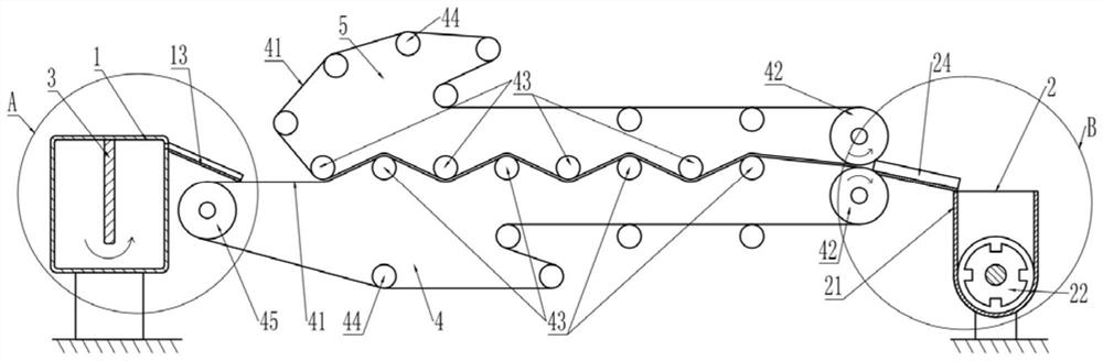
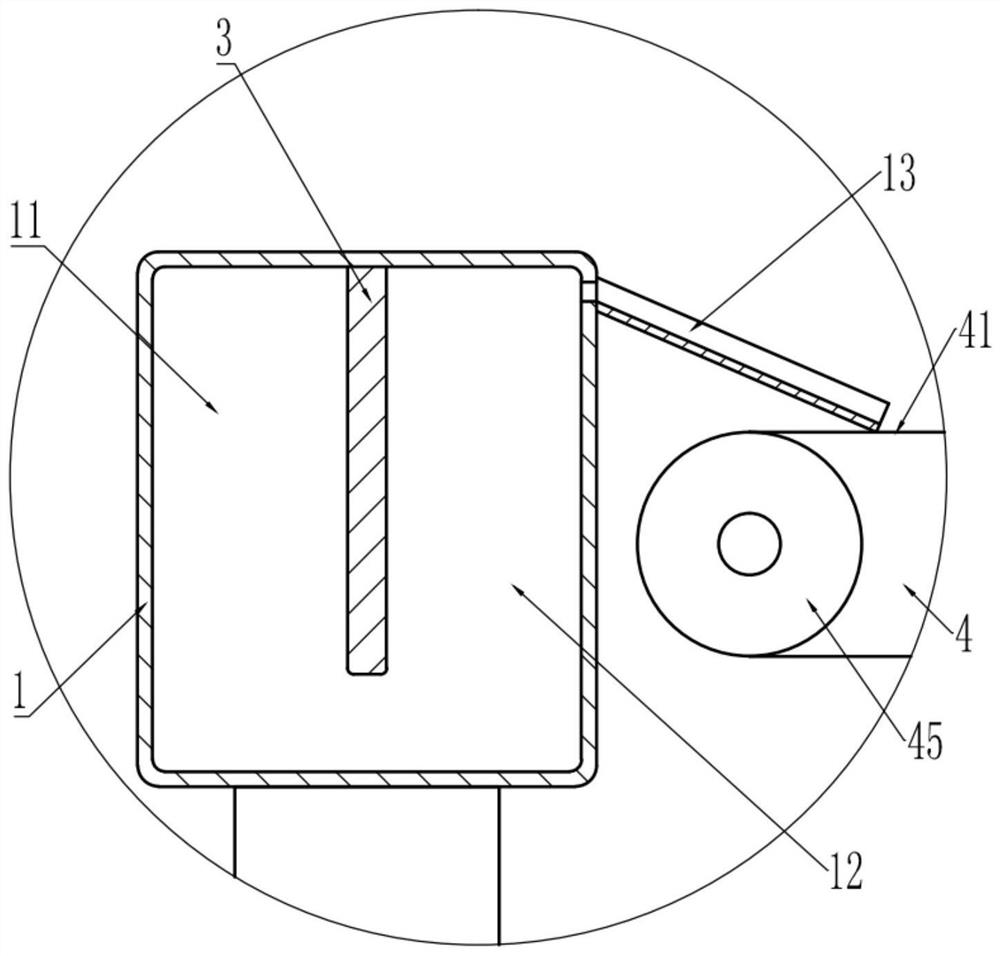
[0035] Embodiment one is basically as attached Figure 1 to Figure 4 Shown:

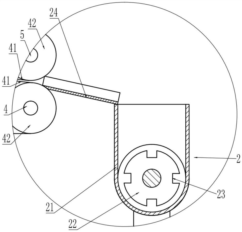
[0036] A device for improving beating concentration, comprising a material box 1, a frame, a traction group and a screw propeller 2, the material box 1, the frame and the screw propeller 2 are installed on the ground, and the traction group is installed on the frame; the material box 1 is welded with a partition 3, the top of the feed box 1 is closed, and an overflow pipe is installed at the bottom of the feed box 1 near the slurry chamber 11. There is a certain distance between the bottom of the partition 3 and the bottom of the feed box 1, and the partition 3 separates the feed box It is divided into a pulp inlet chamber 11 and a pulp outlet chamber 12, and a pulp outlet is opened on the right side wall of the pulp outlet chamber 12 of the head box 1 .

[0037] The traction group includes a first traction group 4 and a second traction group 5, the first traction group 4 is located below the second...

Embodiment 2

[0048] Embodiment two is basically as attached Figure 5 As shown, on the basis of Embodiment 1, Embodiment 2 adds a ventilation pipe 6 that is fixedly connected to the frame by bolts. The papermaking wire 41 of the first traction group 4 passes through the ventilation pipe 6, and the right side of the ventilation pipe 6 communicates. There is an air supply pipe 7 of a blower fan, and several air deflectors 8 are welded in the ventilation pipe 6. The left side of the ventilation pipe 6 bends downward, and the bottom left side of the ventilation pipe 6 is equipped with a collection box 9 for easy water receiving; The top surface and the bottom of the ventilation pipe 6 are all inclined downward from right to left, so that the water falling to the top of the ventilation pipe 6 and the water inside the ventilation pipe 6 can flow into the collection box 9 obliquely downward, so as to facilitate the collection of water .

[0049] The specific implementation process is as follows:...


PUM


Abstract

The invention relates to the technical field of papermaking, and specifically discloses a device for improving the beating concentration, comprising a material box and a traction group. The traction group is provided with a papermaking wire, and the material box is provided with a deflector for facilitating the flow of pulp to the papermaking wire. The group includes a first drawing group and a second drawing group, the first drawing group is located below the second drawing group, the papermaking wire is drawn on both the first drawing group and the second drawing group, and both the first drawing group and the second drawing group include A traction roller and a number of guide rollers, the traction roller is driven by a driver, and the shape of the papermaking wire is wavy when passing through the several guide rollers of the first traction group and the second traction group; it also includes a screw propeller, and the screw propeller includes a conveying pipe and The spiral blade connected in the conveying pipe is rotated, and the conveying pipe is provided with a feeding port, and the feeding port is provided with a drainage plate attached to the papermaking net on the first traction group. This solution is used to solve the problems of low strength and poor toughness of paper produced from pulp with higher beating concentration and low concentration in the prior art.

Description

technical field [0001] The invention relates to the technical field of papermaking, in particular to a device for increasing beating concentration. Background technique [0002] Beating is the shearing, kneading and twisting of papermaking fibers by mechanical force, which causes the primary wall and secondary wall of fiber cells to break, and then makes the fibers absorb water, swell, and separate filaments, so as to meet the quality requirements of papermaking and paper products. The characteristics of beating; the energy consumption of beating occupies a large proportion in papermaking pulping, and the quality of beating directly affects the quality of paper. [0003] In the prior art, after beating of softwood pulp and cotton pulp, etc., it is necessary to use a coarse stock pump to send the pulp from the stock tank into a disc refiner, and rub the fibers in the pulp through the disc refiner to make the fibers of the pulp Further divided into silk brooms, but this type ...

Claims


Application Information

Patent Timeline
Patent Type & Authority Patents(China)
IPC IPC(8): D21D1/30D21F3/02
CPCD21D1/30D21F3/02
Inventor 胡越段爱琴贾海健
Owner 新疆源一科创有限公司
Why Eureka
Try Eureka