Built-in conical surface pre-positioned permanent magnet synchronous coupler

A permanent magnet synchronous and coupling technology, applied in the field of mechanical transmission, can solve the problems of large size and weight of positioning taper sleeve, easy to generate operation risks, etc., to achieve the effect of optimizing installation work, reducing the workload of on-site debugging, and reducing the moment of inertia

Pending Publication Date: 2020-01-10
诸暨和创电机科技有限公司
View PDF1 Cites 0 Cited by
  • Summary
  • Abstract
  • Description
  • Claims
  • Application Information

AI Technical Summary

Problems solved by technology

[0003] The Chinese invention patent (application publication number CN109600016A) proposes a magnetic coupling with a tapered surface positioning structure, which uses an external tapered surface for positioning, but due to the large size and weight of the positioning tapered sleeve, it is easy to cause operational risks

Method used


Image

  • Built-in conical surface pre-positioned permanent magnet synchronous coupler
  • Built-in conical surface pre-positioned permanent magnet synchronous coupler
  • Built-in conical surface pre-positioned permanent magnet synchronous coupler

Examples


Embodiment 1

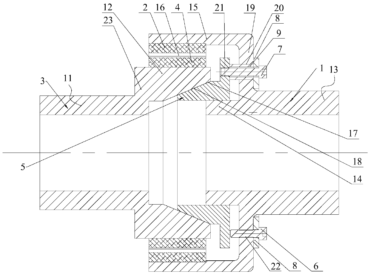
[0065] Such as figure 1 with 2 As shown, a permanent magnet synchronous coupling with built-in conical surface pre-positioning includes two rotors with coincident axes, namely the inner rotor 3 and the outer rotor 1, the inner rotor 3 includes a first body 11, and the first body 11 One end of the outer rotor 1 includes a second body 13, and one end of the second body 13 includes a second annular portion 14 and a third annular portion 15 arranged coaxially, and the third annular portion 15 Located outside the second annular portion 14, and the end surface of the second annular portion 14 is located inside the third annular portion 15, the third annular portion 15 is sheathed on the first annular portion 12, and the third annular portion An outer permanent magnet 2 is installed on the inner side wall of 15, and an inner permanent magnet 4 is installed on the outer side wall of the first annular portion 12, and the outer permanent magnet 2 corresponds to the inner permanent magn...

Embodiment 2

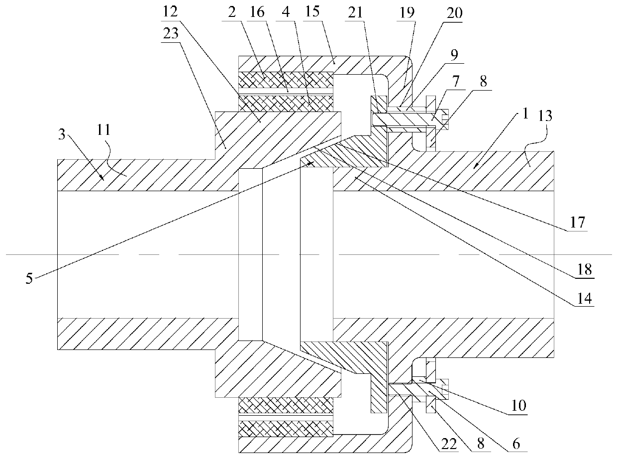
[0083] Such as image 3 with 4 As shown, a permanent magnet synchronous coupling with built-in conical surface pre-positioning includes two rotors with coincident axes, namely the inner rotor 3 and the outer rotor 1, the inner rotor 3 includes a first body 11, and the first body 11 One end of the outer rotor 1 includes a second body 13, and one end of the second body 13 includes a second annular portion 14 and a third annular portion 15 arranged coaxially, and the third annular portion 15 Located outside the second annular portion 14, and the end surface of the second annular portion 14 is located inside the third annular portion 15, the third annular portion 15 is sheathed on the first annular portion 12, and the third annular portion An outer permanent magnet 2 is installed on the inner side wall of 15, and an inner permanent magnet 4 is installed on the outer side wall of the first annular portion 12, and the outer permanent magnet 2 corresponds to the inner permanent magn...

Embodiment 3

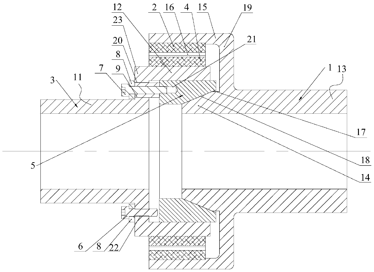
[0097] Such as Figure 5 with 6 As shown, a permanent magnet synchronous coupling with built-in conical surface pre-positioning includes two rotors with coincident axes, namely the inner rotor 3 and the outer rotor 1, the inner rotor 3 includes a first body 11, and the first body 11 One end of the outer rotor 1 includes a second body 13, and one end of the second body 13 includes a second annular portion 14 and a third annular portion 15 arranged coaxially, and the third annular portion 15 Located outside the second annular portion 14, and the end surface of the second annular portion 14 is located inside the third annular portion 15, the third annular portion 15 is sheathed on the first annular portion 12, and the third annular portion An outer permanent magnet 2 is installed on the inner side wall of 15, and an inner permanent magnet 4 is installed on the outer side wall of the first annular portion 12, and the outer permanent magnet 2 corresponds to the inner permanent mag...


PUM


Abstract

The invention discloses a built-in conical surface pre-positioning permanent magnet synchronous coupler. The built-in conical surface pre-positioning permanent magnet synchronous coupler comprises aninner rotor and an outer rotor, wherein the inner rotor is provided with a first annular part, and the outer rotor comprises a second annular part and a third annular part which are coaxially arranged. The end surface of the second annular part is located in the third annular part. The first annular part is sleeved with the third annular part. The built-in conical surface pre-positioning permanentmagnet synchronous coupler further comprises a conical positioning sleeve mounted at the inner side wall of the first annular part or the outer side wall of the second annular part in a sliding manner; the conical positioning sleeve is provided with a first conical surface; the rotor without the conical positioning sleeve is provided with a second conical surface; and the first conical surface and the second conical surface are matched with each other to position the two rotors. According to the built-in conical surface pre-positioning permanent magnet synchronous coupler of the invention, the second annular part and the third annular part which have height difference are designed, so that the conical positioning sleeve can be reliably arranged in the inner rotor or the outer rotor; and the two conical surfaces are positioned at the inner side of an inner permanent magnet and are close to the axes of the rotors; and therefore, the conical positioning sleeve is small in size, light inweight and good in operation stability compared with the prior art.

Description

technical field [0001] The invention relates to the technical field of mechanical transmission, in particular to a permanent magnet synchronous coupling with built-in conical surface pre-positioning. Background technique [0002] Since Mr. Li Guokun put forward the "Li's pull-push theory" in 1979, the synchronous permanent magnet coupling has obtained a theoretical basis. After the 1990s, the rapid development of rare earth permanent magnets has provided for the industrial production of synchronous permanent magnetic couplings. possible. Since then, synchronous permanent magnet couplings have been widely used in the chemical industry, mining, and power generation industries due to their advantages of high efficiency, non-contact, and shock isolation. But the fly in the ointment is that due to the strong magnetic force of the rare earth permanent magnet, during the installation process of the synchronous permanent magnet coupling, due to the effect of the magnetic force, it ...

Claims


Application Information

Patent Timeline
Patent Type & Authority Applications(China)
IPC IPC(8): H02K49/10
CPCH02K49/102H02K49/106H02K2213/03
Inventor 李和良吴伟明阮森杰
Owner 诸暨和创电机科技有限公司
Why Eureka
Try Eureka