Device for insertion into nervous tissue

A device, tissue technology, used in the field of insert components, which can solve problems such as premature dissolution or separation

Pending Publication Date: 2020-01-10
NEURONANO AB
View PDF3 Cites 2 Cited by
  • Summary
  • Abstract
  • Description
  • Claims
  • Application Information

AI Technical Summary

Problems solved by technology

A problem with friction-reducing materials designed to dissolve in body fluids during and on insertion is controlling their premature dissolution or separation during insertion

Method used


Image

  • Device for insertion into nervous tissue
  • Device for insertion into nervous tissue
  • Device for insertion into nervous tissue

Examples


example 1

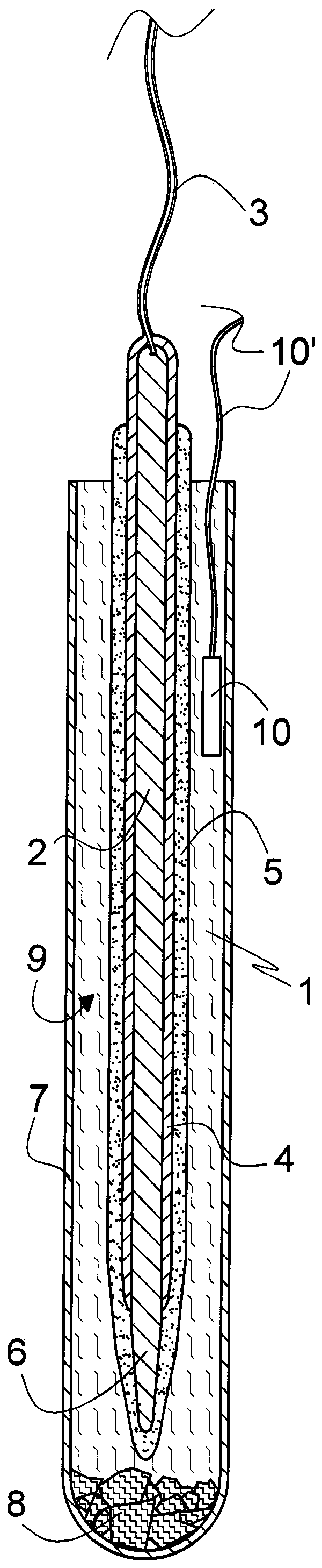
[0096] figure 1 A microelectrode 1 of the art is illustrated comprising an oblong cylindrical metal electrode body 2, such as silver, gold, platinum or iridium, having a narrowed distal tip 6 and attached to it. Flexible electrical leads 3 at the distal end. Apart from the tip 6, the electrode body 2 is electrically insulated by a layer 4 of polymer material, such as polyurethane or parylene C. The electrode body 2 and the tip 6 are covered with a dry gelatin layer 5 of 120 gelatin strength except for a portion extending from the proximal end. The electrode 1 is shown inserted into a test tube shaped cooling container 7 with its distal tip 6 at the front. A container 7, which may be insulated (not shown), is loaded with dry ice 8 provided at its bottom. Electrode 1 is cooled by gaseous carbon dioxide 9 evaporated from dry ice 8 . The temperature of the carbon dioxide 9 gas in the container is monitored by a thermocouple 10 ; alternatively or additionally, the temperature o...

example 2

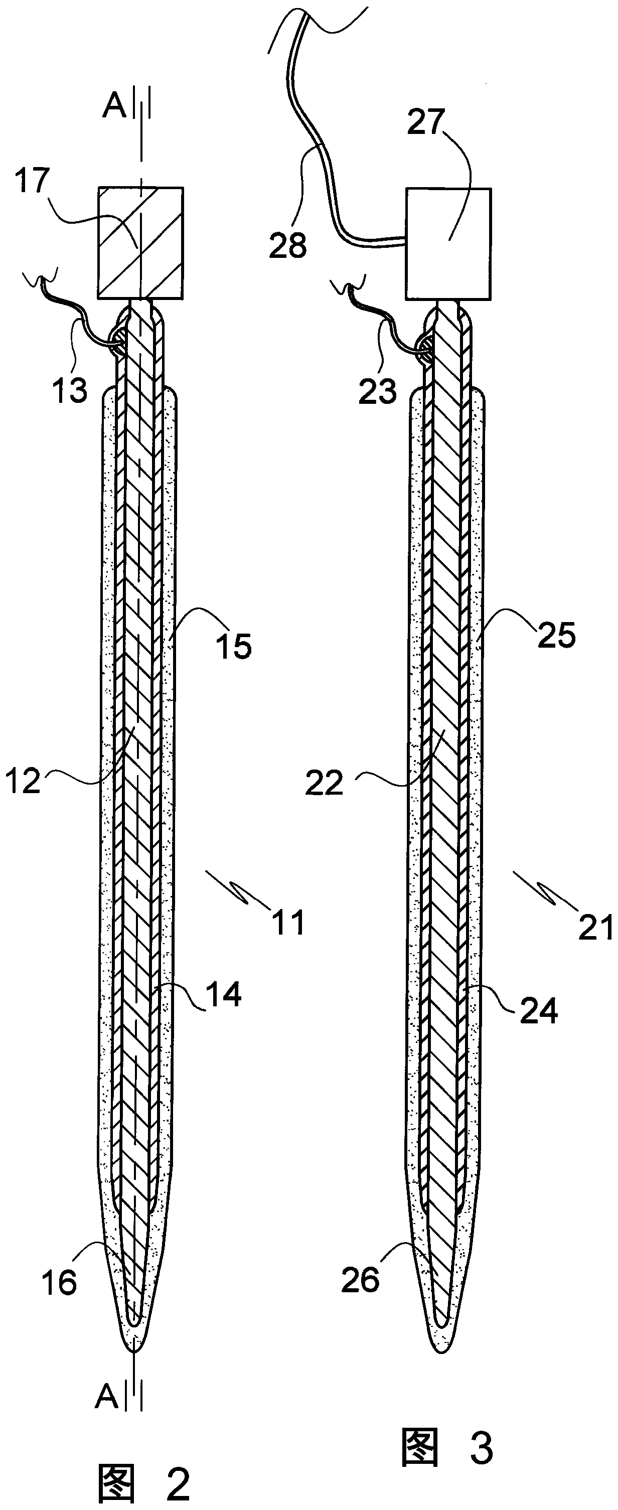
[0099] figure 2 The design of the microelectrode 11 according to the invention shown in axial section A-A basically corresponds to the design of the microelectrode 1 of Example 1, except that the cooling means in the form of a heat sink 17 is in thermal communication between the electrodes. The proximal end of the body 12 is attached to the electrode body 12 . Before implanting the microelectrode 11, the heat sink 17 is cooled in combination with the electrode 11 or alone to a low temperature, such as the temperature to which the electrode 11 is cooled or even lower or significantly lower. With the heat sink 17 at a lower temperature than the electrode 11, heat flows from the electrode body 12 to the heat sink 17, thereby cooling the electrode 11 and thus delaying the process of covering most of the Swelling and dissolution of the gel-like or other expandable layer 15 on the insulating layer 14 of the electrode body 12 . Suitable heat sink materials include steel, copper, c...

example 3

[0101] image 3 in and figure 2 The design of the microelectrode 21 of the present invention shown in the axial section corresponding to the axial section A-A of the embodiment basically corresponds to the design of the microelectrode 11 of Example 2, except that it has the form of a Peltier element 27 A cooling device (rather than a heat sink) is attached to the electrode body 22 at its proximal end in thermal communication. The Peltier element 27 is powered via an insulated flexible lead 28 . The microelectrode 21 comprises correspondingly arranged insulating and expandable layers 24 , 25 on the electrode body 22 , the narrowed distal end portion 26 of the electrode body 22 being similarly free of the insulating layer 24 . The electrode body 22 is electrically connected to a power source (not shown) and / or an instrument (not shown) for detecting voltage changes by means of electrically insulated flexible leads 23 . Upon completion of the insertion procedure, the cooled t...


PUM


Abstract

A device selected from microelectrode, temperature sensor, optical sensor, optical fibre, temperature control element, and microdialysis probe for insertion into soft tissue comprises a body with a distal terminal section and a layer of an agent such as gelatin capable of forming a gel with aqueous body fluid on the terminal section. The terminal section and the gel -forming layer have a temperature of more than 30 degrees centigrade below body temperature during a period of time prior and up to insertion. Also disclosed is method of insertion, an insertion assembly and a use of the device.

Description

[0001] field of invention [0002] The present invention relates to a diagnostic and / or therapeutic device for insertion into soft tissue, in particular neural or endocrine tissue, an insertion assembly comprising the device and an insertion device, a method of inserting the device into neural tissue, and the use of the device . A preferred embodiment of the device is a microelectrode. Other embodiments of the device are temperature and optical sensors, optical fibers, temperature control elements, microdialysis probes, and the like. [0003] Background of the invention [0004] Insertion of microelectrodes or other devices into soft tissue, particularly neural or endocrine tissue, is accompanied by damage to that tissue. To ensure the proper functioning of the electrodes at the time of insertion, it is critical to prevent excessive trauma. Various measures can be taken to minimize damage, such as microelectrode designs that emphasize electrode diameter reduction and coating...

Claims


Application Information

Patent Timeline
Patent Type & Authority Applications(China)
IPC IPC(8): A61N1/05A61B5/04A61N1/36A61N1/372A61B5/24A61B5/296
CPCA61N1/0531A61N1/0551A61B5/25A61B2562/0209A61B2560/063A61B5/293A61B5/0084A61B5/01A61B5/14528A61F7/00A61F2007/0075A61F2007/0095A61B5/24A61B5/6877A61N1/05A61N1/3605A61N1/37205A61N1/375A61B2562/16A61B2562/028A61B2562/0271A61B17/3468A61F7/007A61F7/02A61F2007/0219
Inventor J·舒恩伯格
Owner NEURONANO AB
Why Eureka
Try Eureka