
A kind of cervical puncture biopsy forceps and using method thereof

A puncture biopsy and cervical technology, applied in the field of biopsy forceps, can solve problems such as inconvenient use, errors, and lighting blind spots, and achieve the effects of ensuring accuracy, easy use, and easy operation

Active Publication Date: 2020-10-02
SHANDONG UNIV
View PDF10 Cites 0 Cited by
  • Summary
  • Abstract
  • Description
  • Claims
  • Application Information

AI Technical Summary

Problems solved by technology

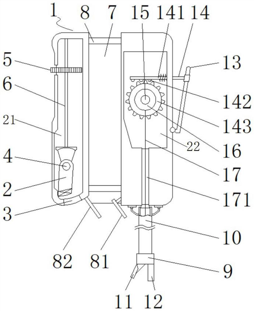
[0004] 1. In order to facilitate the doctor to clearly observe the human body sampling area, the biopsy forceps used for cervical treatment are generally equipped with corresponding lights on the outside, but because this kind of lights can only be set on the outside, and the illumination angle cannot be adjusted, Therefore, there are still lighting blind spots in actual use;
[0005] 2. The forceps head is an important part of the biopsy forceps. Because it can perform puncture and sampling operations under the operation of medical staff, the accuracy of its position inside the human body is very important, which determines whether the medical staff can perform biopsy in as few times as possible. However, due to the unreasonable design of the overall structure of the existing biopsy forceps, the medical staff cannot directly observe the relative position between the biopsy forceps and the lesion without the help of external instruments, which is very inconvenient to use ;
[0006] 3. The existing needle tubes, clamp heads, and biopsy forceps are all fixedly connected, so that when the medical staff adjusts the position of the clamp heads, the existing equipment such as the camera used to observe the position of the clamp heads will also move synchronously, which is easy It leads to the operation error of medical staff and the wrong sampling position, which increases the pain of the patient, and the design is unreasonable

Method used


Image

  • A kind of cervical puncture biopsy forceps and using method thereof
  • A kind of cervical puncture biopsy forceps and using method thereof
  • A kind of cervical puncture biopsy forceps and using method thereof

Examples


Embodiment Construction

[0043] The present invention will be further described below in conjunction with the accompanying drawings and embodiments.

[0044] It should be noted that the following detailed description is exemplary and intended to provide further explanation of the present invention. Unless defined otherwise, all technical and scientific terms used herein have the same meaning as commonly understood by one of ordinary skill in the art to which this invention belongs.

[0045] It should be noted that the terminology used here is only for describing specific implementations, and is not intended to limit the exemplary implementations according to the present application. As used herein, unless the context clearly dictates otherwise, the singular is intended to include the plural, and it should also be understood that when the terms "comprising" and / or "comprising" are used in this specification, they mean There are features, steps, operations, means, components and / or combinations thereof...


PUM


Abstract

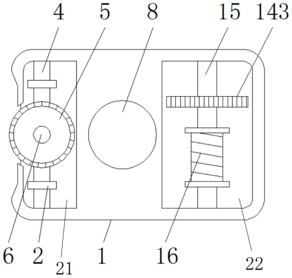
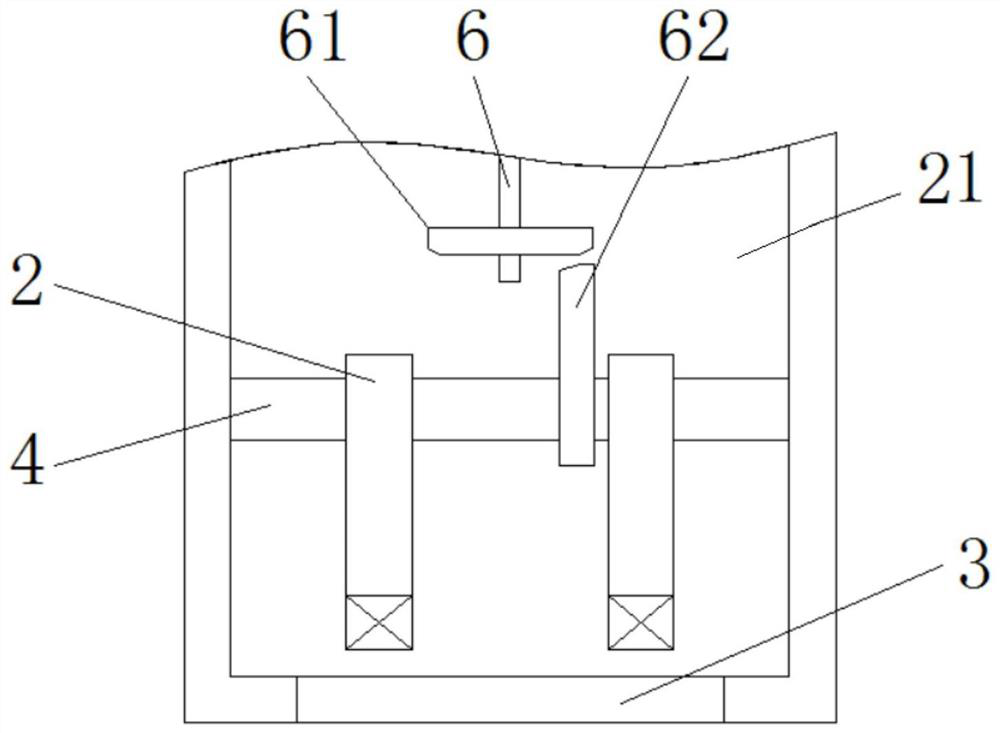
The invention discloses a cervical puncture biopsy forceps and a using method thereof. The cervical puncture biopsy forceps includes a housing, a first cavity located in the left half part of the housing, a square second cavity located in the right half part of the housing, a third cavity located in the middle of the housing, and a forceps head device located at the bottom of the housing and on the same side as the second cavity; a lighting device is arranged in the first cavity, and a forceps head adjustment device is arranged in the second cavity; the lighting device includes a lighting lamp, a first rotating shaft, an adjusting wheel, and a vertical rod; the forceps head adjustment device includes a transverse rod, a second rotating shaft, a wire roller, a gear, and a drawstring; and the forceps head device includes a needle tubing, a forceps head mounted at the bottom of the needle tubing, and a cutter and an accommodating plate mounted on the forceps head.

Description

technical field [0001] The invention relates to the technical field of biopsy forceps, in particular to a cervical puncture biopsy forceps which are convenient for adjusting the light angle and a method for using the same. Background technique [0002] Biopsy forceps is a kind of medical inspection and sampling equipment, which refers to the minimally invasive sampling operation of living tissue on the surface of the normal human body or inside the body, using the protruding forceps and the cutter, to the designated area of ​​the human body. Compared with the traditional diagnosis and treatment Methods, the popularity of this type of equipment has greatly improved the accuracy of doctors' diagnosis and treatment of patients' conditions. Therefore, biopsy forceps are also widely used in the treatment and diagnosis of gynecological cervical diseases combined with dilators. [0003] The inventor found during the research and development process that this type of biopsy forceps ...

Claims


Application Information

Patent Timeline
Patent Type & Authority Patents(China)
IPC IPC(8): A61B10/06A61B10/04F21V21/26F21W131/20
CPCA61B10/0291A61B10/04A61B10/06F21V21/26F21W2131/20
Inventor 李玮袁双虎韩毅孟祥伟马志祥
Owner SHANDONG UNIV
Learn More