An intelligent lightning protection optical box

An optical communication box, intelligent technology, applied in the direction of optics, light guide, optical components, etc., can solve the problems of general lightning protection function of optical communication box, device damage, etc., and achieve the effect of improving anti-corrosion performance, stable structure, and preventing lightning damage

Active Publication Date: 2020-11-24
湖南省通信建设有限公司
View PDF6 Cites 0 Cited by
  • Summary
  • Abstract
  • Description
  • Claims
  • Application Information

AI Technical Summary

Problems solved by technology

[0003] The lightning protection function of the current optical communication box is average, and once it is struck by lightning, it is easy to cause almost complete damage to the internal devices

Method used


Image

  • An intelligent lightning protection optical box
  • An intelligent lightning protection optical box
  • An intelligent lightning protection optical box

Examples


Embodiment 1

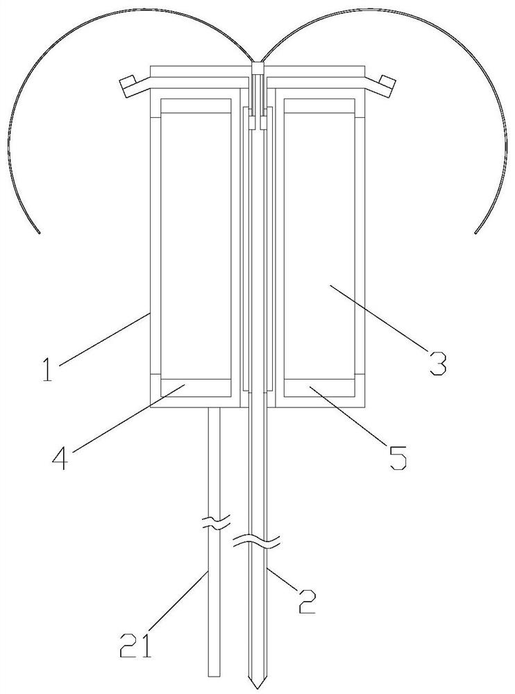
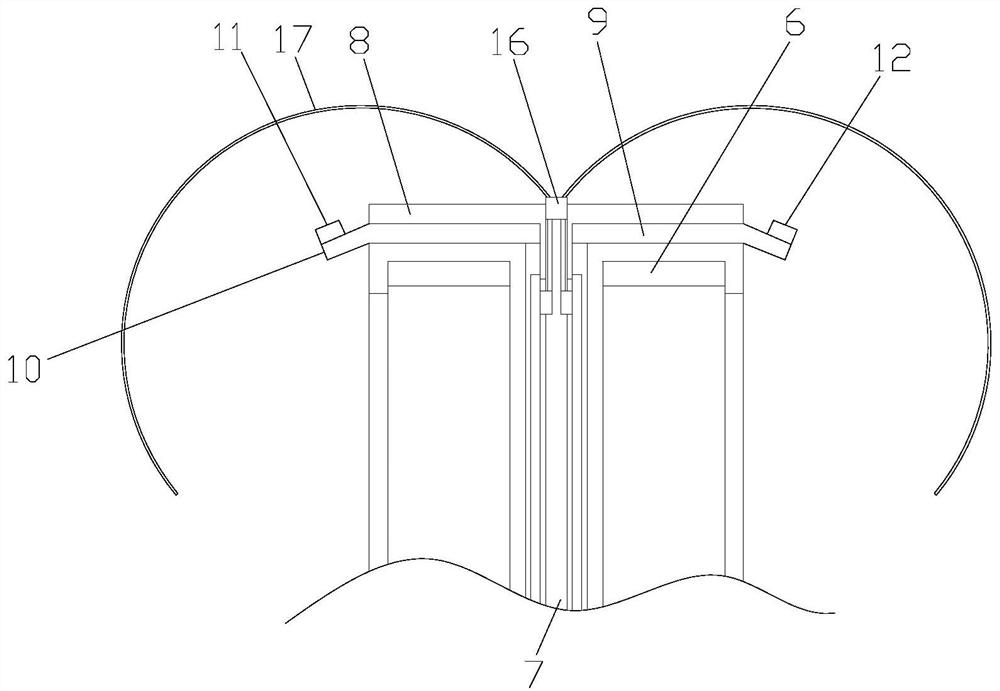
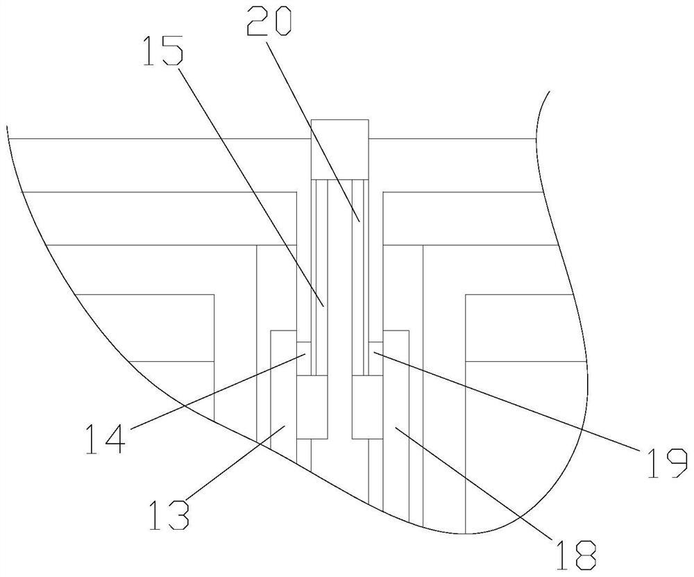
[0025] Such as Figure 1-3 As shown, an intelligent lightning protection light delivery box includes an insulating box 1 and a grounding rod 2. The insulating box 1 is cylindrically arranged, and the middle part of the insulating box 1 is provided with a first perforation (not shown). And constitute a tubular structure, the insulating box 1 is formed with an annular storage chamber 3, the storage chamber 3 is provided with a control device 4, a battery 5 and an anti-surge protector 6, and the middle part of the grounding rod 2 is provided There is a second perforation 7, the grounding rod 2 is inserted into the first perforation, the grounding rod 2 is provided with a protective plate 8, the protective plate 8 is located directly above the insulating box 1, and the protective plate 8 and the insulating An insulating plate 9 is arranged between the box bodies 1, and the protective plate 8 and the insulating box body 1 are fixedly connected with the insulating plate 9. The rainw...

Embodiment 2

[0028] Such as Figure 1-3 As shown, an intelligent lightning protection light delivery box includes an insulating box 1 and a grounding rod 2. The insulating box 1 is cylindrically arranged, and the middle part of the insulating box 1 is provided with a first perforation (not shown). And constitute a tubular structure, the insulating box 1 is formed with an annular storage chamber 3, the storage chamber 3 is provided with a control device 4, a battery 5 and an anti-surge protector 6, and the middle part of the grounding rod 2 is provided There is a second perforation 7, the grounding rod 2 is inserted into the first perforation, the grounding rod 2 is provided with a protective plate 8, the protective plate 8 is located directly above the insulating box 1, and the protective plate 8 and the insulating An insulating plate 9 is arranged between the box bodies 1, and the protective plate 8 and the insulating box body 1 are fixedly connected with the insulating plate 9. The rainw...


PUM


Abstract

The invention discloses an intelligent lightning-protection optical cable cross-connecting box, which comprises an insulating box body and a grounding rod. The insulating box body is cylindrical; themiddle part of the insulating box body is provided with a first through hole and forms a tubular structure. An annular accommodating cavity is formed in the insulating box body. A control device, a storage battery and an anti-surge protector are arranged in the storage cavity. A second through hole is formed in the middle of the grounding rod; the grounding rod is inserted into the first through hole; a protection plate is arranged on the grounding rod; the protection plate is located right above the insulating box body; an insulating plate is arranged between the protection plate and the insulating box body; the protection plate and the insulating box body are fixedly connected with the insulating plate; a rainwater guide plate is arranged on the insulating plate; a pickup device and a raindrop sensor are arranged on the rainwater guide plate; and a first mounting groove is formed in the hole wall of the first through hole. The intelligent lightning-protection optical cable cross-connecting box can be effectively prevented from being destroyed by thunder and lightning.

Description

technical field [0001] The invention relates to an intelligent lightning protection optical delivery box. Background technique [0002] The optical cable transfer box, also known as the street cabinet, is usually placed on the main optical cable for branching the optical cable. It is a passive device and has similar functions to the original copper cable transfer box. After passing through the optical cable transfer box, it is divided into several small logarithmic optical cables in different directions. Of course, this function can also be realized by the optical cable splice box, but the difference is that the optical cable transfer box can realize the jumping of optical cables, and can also be used for testing and maintain. Generally, the optical cable transfer box is the division point of the feeder optical cable and the distribution optical cable. [0003] The lightning protection function of the current optical communication box is average, and once it is struck by l...

Claims


Application Information

Patent Timeline
Patent Type & Authority Patents(China)
IPC IPC(8): G02B6/44
CPCG02B6/4446
Inventor 叶才青张威于洪海
Owner 湖南省通信建设有限公司
Why Eureka
Try Eureka