Water level gauge switch valve for intelligent water conservancy system

An on-off valve, water level gauge technology, applied in electrical switches, electrical components, circuits, etc., can solve problems such as buttons are easily pressed by mistake, abnormal opening or closing, affecting data collection, etc., to achieve easy switching, ensure stable power supply, prevent The effect of accidental power-on or shutdown

Pending Publication Date: 2020-01-14
SHENZHEN WEINEIDE SOFTWARE DEV CO LTD
View PDF0 Cites 0 Cited by
  • Summary
  • Abstract
  • Description
  • Claims
  • Application Information

AI Technical Summary

Problems solved by technology

Later, some water level gauges were made into tubes. In this type of water level, the outer tube is equipped with a sensor or circuit board for measuring the water level, and the sealing cover on the top of the outer tube is set as a switch. The traditional switch is mostly button type. Buttons are easy to accidentally press and cause abnormal opening or closing
However, with the development of the smart water conservancy industry, the water level gauge needs to run continuously for a long time to ensure the real-time data collection of the smart water conservancy platform. Therefore, the traditional button switch is easy to cause abnormal opening or closing, which affects data collection.

Method used


Image

  • Water level gauge switch valve for intelligent water conservancy system
  • Water level gauge switch valve for intelligent water conservancy system
  • Water level gauge switch valve for intelligent water conservancy system

Examples


Embodiment Construction

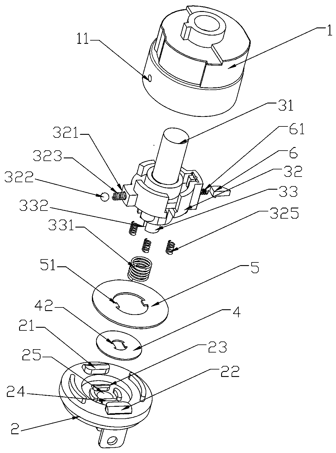
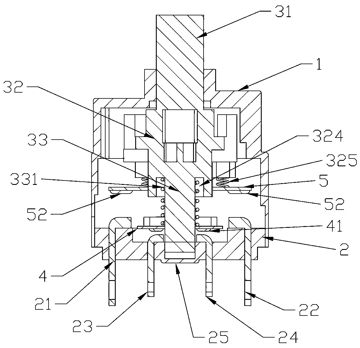
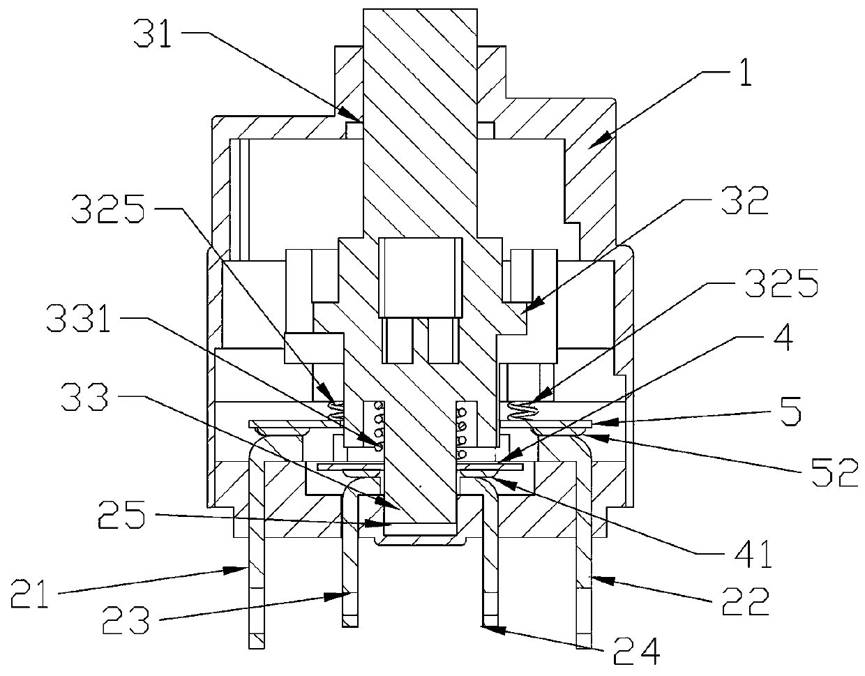
[0022] A water level switch valve for a smart water conservancy system, comprising a casing 1 and a bottom plate 2, the casing 1 is covered on the bottom plate 2, and also includes a valve core, a small contact piece 4 and a large contact piece 5; the valve core Set in the casing; the valve core includes an operating end 31, a limiting end 32 and a contact end 33 from top to bottom; the operating end 31 and the contacting end 33 are arranged at both ends of the limiting end 32; the small contact piece 4 is set on the contact end 33; the middle part of the lower end of the limit end 32 is provided with a circular groove 324; the large contact piece 5 is set outside the circular groove 324; the bottom plate 2 is provided with the first upper contact piece 21, the second The second upper contact piece 22 is in contact with the large contact piece 5, and the first lower contact piece 23 is in contact with the second lower contact piece 24 and the small contact piece 4; in this embo...


PUM


Abstract

The invention provides a water level gauge switch valve for an intelligent water conservancy system, which comprises a shell and a bottom plate, wherein the shell covers the bottom plate. The water level gauge switch valve is characterized by further comprising a valve element, a small contact piece and a large contact piece; the valve core is arranged in the shell; the valve element comprises anoperation end, a limiting end and a contact end from top to bottom; the operation end is arranged at the upper end of the limiting end; the small contact piece sleeves the contact end; a circular groove is formed in the middle of the lower end of the limiting end; the large contact piece sleeves the outside of the circular groove; the bottom plate is provided with a first upper contact piece and asecond upper contact piece which are in contact fit with the large contact piece, and a first lower contact piece and a second lower contact piece which are in contact fit with the small contact piece; the first upper contact piece/the second upper contact piece is electrically connected with the first lower contact piece/the second lower contact piece; a limiting hole is formed in one side of the limiting end; a limiting ball is arranged in the limiting hole; the limiting ball is connected with the limiting hole through a limiting spring; the shell is provided with a round hole correspondingto the limiting ball; the contact end is provided with a compression spring; one end of the compression spring is fixed with the circular groove, and the other end is connected with the small contactpiece; the bottom plate is provided with a groove corresponding to the contact end. Switching can be controlled by rotating, so that a water level gauge is easier to switch between power-on and power-off.

Description

technical field [0001] The invention belongs to the field of water level measuring equipment, and in particular relates to a water level gauge switch valve limit structure for a smart water conservancy system used in the smart water conservancy industry. Background technique [0002] The water level gauge is a commonly used monitoring equipment in the water conservancy industry. Traditionally, there are float type, optical fiber water level gauge, ultrasonic water level gauge and other water level gauges. Later, some water level gauges were made into tubes. In this type of water level, the outer tube is equipped with a sensor or circuit board for measuring the water level, and the sealing cover on the top of the outer tube is set as a switch. The traditional switch is mostly push-button type. The button is easy to accidentally press and cause abnormal opening or closing. However, with the development of the smart water conservancy industry, the water level gauge needs to ru...

Claims


Application Information

Patent Timeline
Patent Type & Authority Applications(China)
IPC IPC(8): H01H25/06
CPCH01H25/06
Inventor 郑育彪章和盛
Owner SHENZHEN WEINEIDE SOFTWARE DEV CO LTD
Why Eureka
Try Eureka