
Electric power supply control device, heating device and fixing device

a technology of electric power supply and control device, which is applied in the direction of electric/magnetic/electromagnetic heating, instruments, electrographic processes, etc., can solve the problems of increased standby period, deterioration of use convenience, and difficulty in increasing the supply power of heating

Inactive Publication Date: 2010-03-23
RICOH KK
View PDF28 Cites 11 Cited by
  • Summary
  • Abstract
  • Description
  • Claims
  • Application Information

AI Technical Summary

Benefits of technology

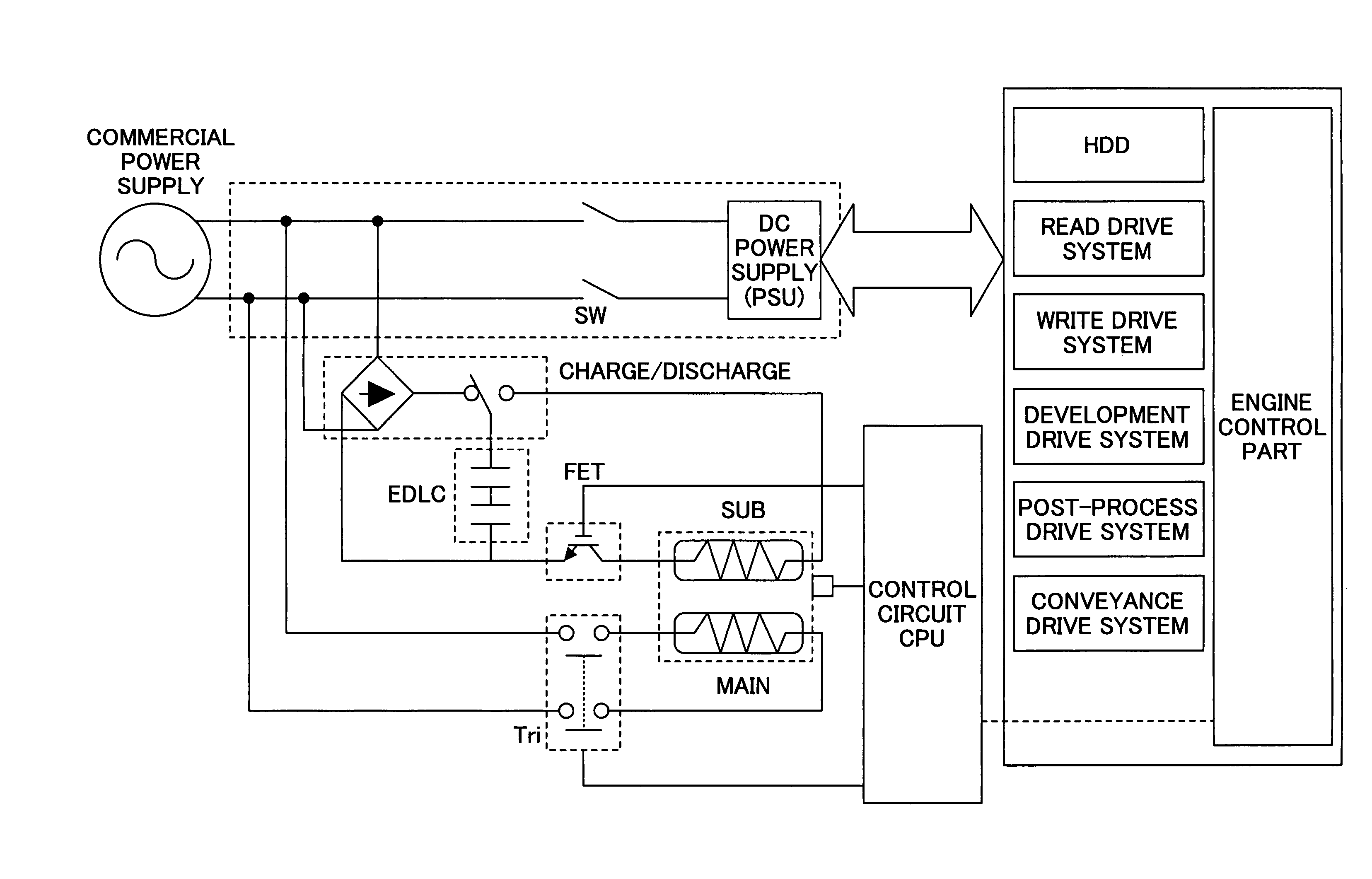
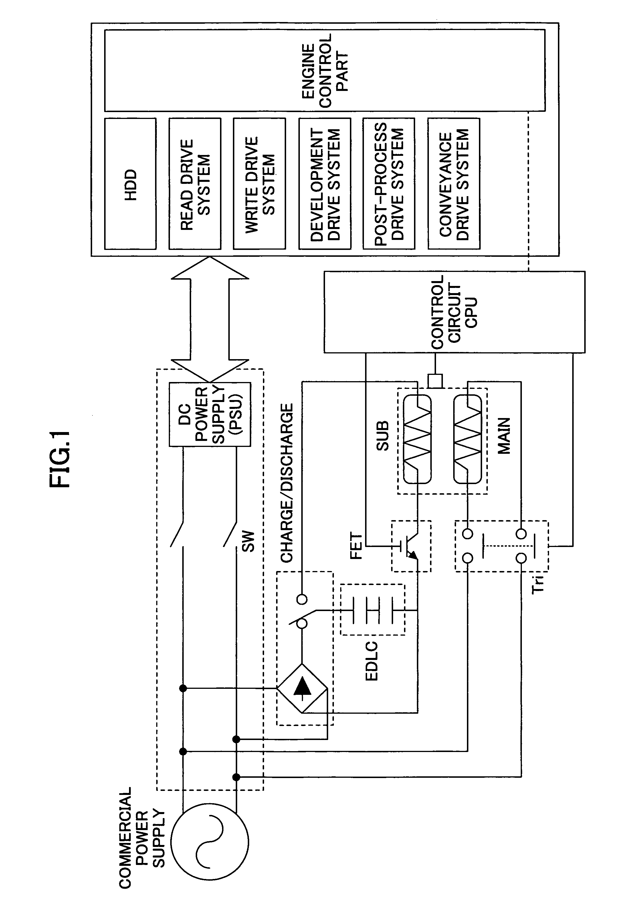
[0024]A more specific object of embodiments of the present invention is to provide an electric power supply control device of a heating device and a fixing device, which is small and has a high-safety while enabling a temperature rise in a short time by increasing an electric power usable by heating means.
[0025]Another object of embodiments of the present invention is to provide an electric power supply control device of a heating device and a fixing device, which can supply a stable electric power to heating means even when a device having a small charge current is used.
[0026]A further object of embodiments of the present invention is to provide a fixing device and an image forming apparatus, which is small and has a high-safety while enabling a temperature rise in a short time by increasing an electric power usable by heating means and capable of achieving a high-speed printing.
[0028]According to the above-mentioned electric power supply control device, electric power is supplied to the heat-generating member from only the main electric power supply device. That is, there is no need to provide an auxiliary heater to which electric power is supplied from the auxiliary electric power supply device. Additionally, a maximum electric power to the heat-generating member can be reduced, which improves safety while attempting miniaturization of the device. Further, since the heat-generating member does not receive electric power from the auxiliary electric power supply device, an amount of electric power required to the auxiliary electric power supply device can be reduced. If the auxiliary electric power supply device is constituted by a plurality of capacitors, a capacitance of each of the capacitors can be increased to reduce a number of cells, which enables attempting further miniaturization.

Problems solved by technology

Thus, the standby period is increased and use convenience is deteriorated.
Thus, it is difficult to increase a supply power to the heating means by a general commercial power supply alone.
Although the low heat capacity of the heating means is effective in the middle and low print speed range, it is difficult to maintain the temperature of the heating means at a predetermined temperature is the heat capacity of the heating member is small since an amount of heat taken by a recording material from the heating means is larger than an amount of heat given to the heating means as a number of recording materials supplied per unit time is large in a high speed print range higher than 60 cpm (60 sheets / 1 minute).
In an image forming apparatus, such a decrease in the heating means may cause a fixation failure.
However, it is necessary to change a power supply source at an installation location, and, thus, it is not a general solution.
Additionally, there is an apparatus put into practice that used two lines of 100V / 15 A to increase a total supply power, but it is difficult to install the apparatus unless receptacles of two separate lines are provided close to the installation location.
Thus, conventionally, it is difficult to increase the upper limit of the supply power so as to raise the temperature of the heat roller (heating means) in a short time.
However, the secondary battery deteriorates and the capacity thereof is reduced while repeating charge and discharge, and a service life is shortened as a discharge is carried out with a large current.
This requires labor of replacing the battery, and a running cost such as a battery cost is very high.
Further, from viewpoint of a charge time, since it requires a long time to charge a large-capacity battery, such a battery cannot be used for an application in which charge and discharge are repeated in a day.
Thus, it is difficult in practice to use the secondary battery.
According to the method of supplying an electric power to the auxiliary heater such as disclosed in the Patent Document 1, the auxiliary heater is needed in addition to the main heater as a heat-generating member of the heating means, and, thus, there is a limitation in reduction of a size of the heating means.
Thus, it is difficult to use a charge device having a relatively small capacity such as an electric double layer capacitor, and a charge device which cannot acquire a sufficient capacity such as a capacitor cannot be used as an auxiliary power supply device.
Additionally, it is difficult to miniaturize the charge device by reducing the charge current to the battery.
Thus, it is not suitable for an application of an image forming apparatus of a short time temperature raise or a high-speed print.
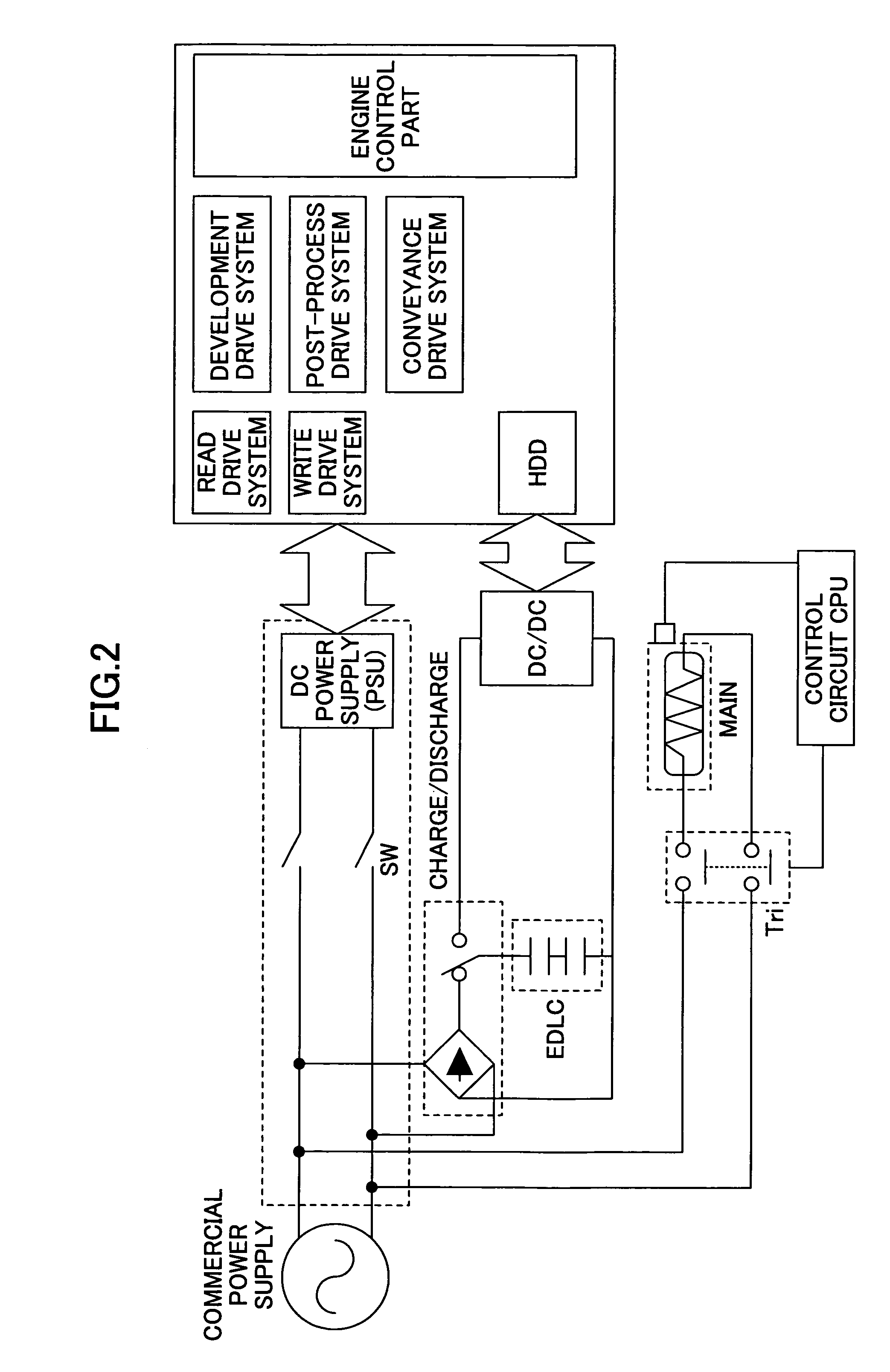
Additionally, if the image forming apparatus is equipped with a device such as a hard disk drive or a stapler, which requires a large electric power instantaneously from an auxiliary power supply device, it is difficult to increase an electric current supplied to the heating means.
Thus, it is not suitable for an application to an image forming apparatus of a short time temperature raise or a high-speed print.
Moreover, although a system can be achieved within a limited electric power of a commercial power supply line by supplying a required electric power from an auxiliary power supply even in a case where a large electric power is required instantaneously for operating a hard disk drive (HDD) or a stapler such as shown in FIG. 4, it is difficult to increase an amount of power supply to the fixing device in such an application to supply an auxiliary electric power to a specific device, and the short time temperature raise or a high-speed print cannot be achieved.

Method used


Image

  • Electric power supply control device, heating device and fixing device
  • Electric power supply control device, heating device and fixing device
  • Electric power supply control device, heating device and fixing device

Examples


Embodiment Construction

[0049]A description will be given below, with reference to the drawings, of embodiments of the present invention.

[0050]FIG. 5 is an outline diagram of an image forming apparatus to which the present invention is applied. In FIG. 5, the image forming apparatus is provided with a drum-shaped photosensitive member 41 as an electrostatic latent image carrier (image carrier) in a main body thereof. The photosensitive member 41 is configured and arranged to be rotated by a drive motor (not shown in the figure) in a clockwise direction indicated by an arrow in the figure. Arranged around the photosensitive member 41 in a rotating direction of the photoconductive member 41 are a charge device 42 uniformly charging the surface of the photosensitive member 41, a development device 44 having a development roller 44a for developing the latent image on the photosensitive member 41, a transfer device 48 for transferring the image (toner image) on the photosensitive member 41 onto a recording pape...


PUM


Abstract

An electric power supply part supplies electric power to a heat-generating member and a power requiring part. A control part controls electric power supplied to the heat-generating member and the power requiring part. A first mode is to supply electric power to the heat-generating member from only a main electric power supply device and to the power requiring part from both the main electric power supply device and an auxiliary electric power requiring part. A second mode is to supply electric power to the heat-generating member and the power requiring part from only the main electric power supply device and causing electric power supplied to the heat-generating member to be smaller than a rated electric power of the heat-generating member. The electric power supplied to the heat-generating member in the first mode is caused to be larger than the electric power supplied to the heat-generating member in the second mode.

Description

BACKGROUND OF THE INVENTION[0001]1. Field of the Invention[0002]The present invention generally relates to power supply control device and, more particularly, to a power supply control device for supplying an electric current to a heating element or a part requiring power supply and a heating device and a fixing device to which an electric current is supplied by the power supply control device.[0003]2. Description of the Related Art[0004]An image forming apparatus represented by a copy machine, a printer, a facsimile, a combination machine of the aforementioned or the like forms an image by image forming part and transfers the formed image onto a sheet-like recording material such as a recording paper or an OHP sheet. Various recording methods are materialized as an image recording method used in the image forming apparatus. From among those methods, an electrophotographic method is used widely by the above-mentioned apparatuses from viewpoints of high-speed, high image quality and ...

Claims


Application Information

Patent Timeline
Patent Type & Authority Patents(United States)
IPC IPC(8): H05B6/14G03G15/00G03G15/20
CPCG03G15/2039G03G15/80
Inventor KISHI, KAZUHITOOKAMOTO, MASAMI
Owner RICOH KK
Learn More