Fishpond aerator based on triboelectricity principle

A technology of friction electricity generation and aeration machine, which is applied in fish farming, application, animal husbandry, etc., can solve the problems of low oxygenation efficiency and poor effect, increase the contact area, improve the efficiency of dissolved oxygen, and inhibit mutual amalgamation Effect

Inactive Publication Date: 2020-01-17
丁晶
View PDF4 Cites 5 Cited by
  • Summary
  • Abstract
  • Description
  • Claims
  • Application Information

AI Technical Summary

Problems solved by technology

[0005] The purpose of the present invention is to provide a fish pond aerator with high efficiency and good oxygenation effect based on the principle of friction generation

Method used


Image

  • Fishpond aerator based on triboelectricity principle
  • Fishpond aerator based on triboelectricity principle
  • Fishpond aerator based on triboelectricity principle

Examples


Embodiment 1

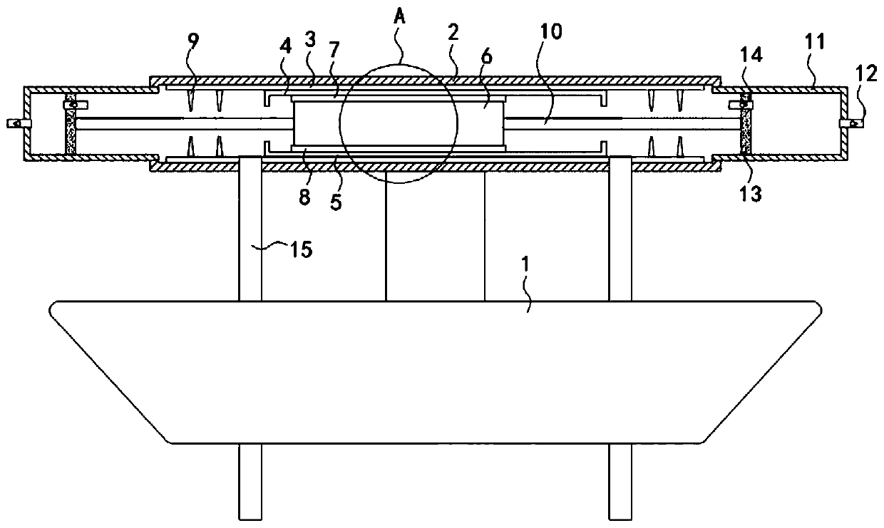
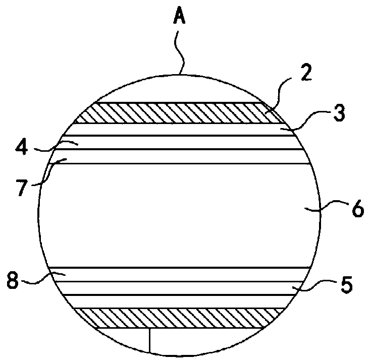
[0017] Such as Figure 1-2 As shown, a fish pond aerator based on the principle of friction electricity generation includes a floating seat 1, the upper end of the floating seat 1 is fixedly connected to a housing 2 through a support column, and the upper top surface and the lower bottom surface of the housing 2 are fixedly connected. There is an induction plate 3, an upper friction plate 4 and a lower friction plate 5 are respectively fixedly connected to the opposite side walls of the two induction plates 3, the lower surface of the upper friction plate 4 is adhered with silk cloth, and the lower friction plate 5 is adhered with fur , the housing 2 is provided with a sliding block 6, the upper friction plate 4, the lower friction plate 5 and the sliding block 6 are all made of insulating materials, the upper end and the lower end of the sliding block 6 are respectively fixedly connected with a glass mesh plate 7 and a rubber mesh plate 8. The glass mesh plate 7 and the rubbe...

Embodiment 2

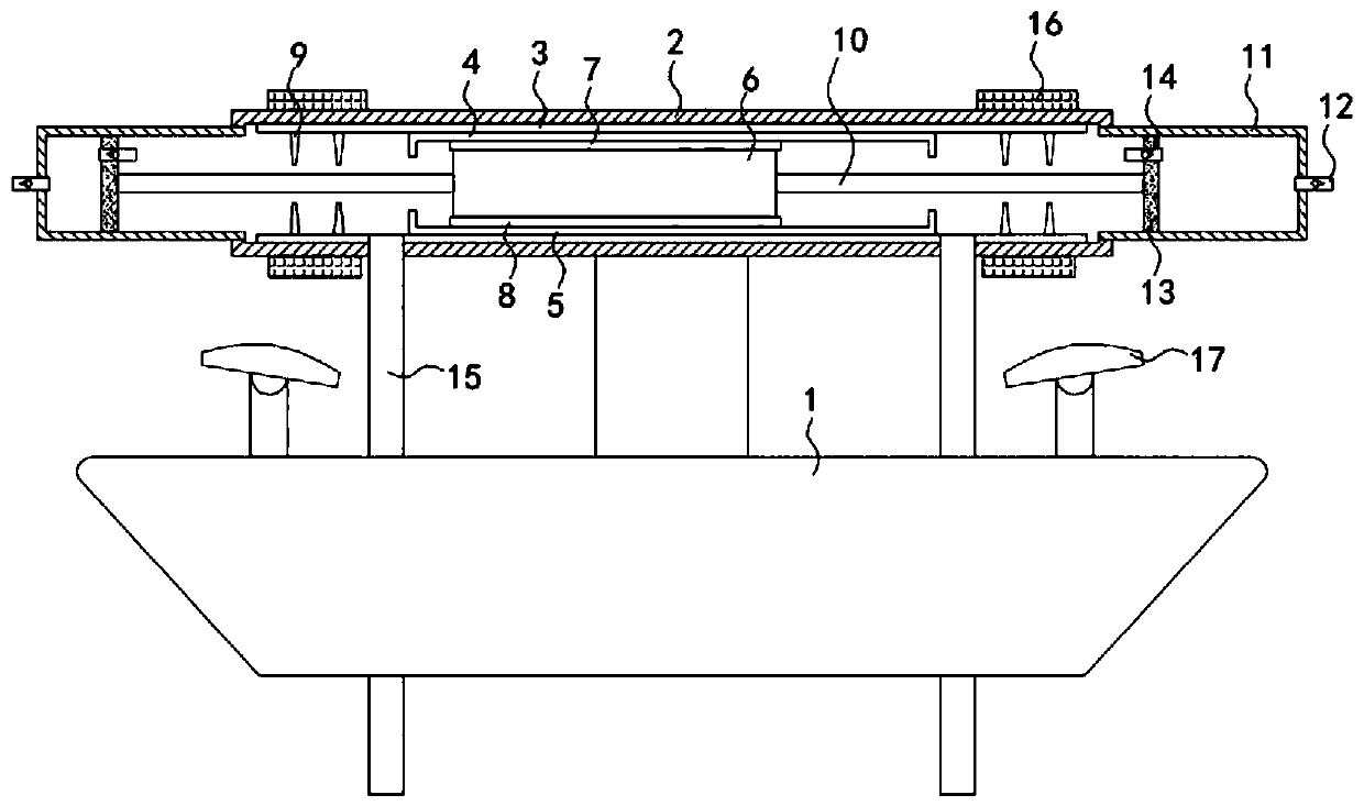
[0022] Such as image 3 As shown, the difference between this embodiment and Embodiment 1 is that the housing 2 is made of a transparent material, and the outer shell 2 is fixedly sleeved with an annular light baffle 16, which is a red translucent light baffle, which acts as To achieve a good anti-glare effect and avoid affecting the normal work of the farmers, the upper surface of the floating seat 1 is fixedly connected with two reflectors 17, and the mirror surface of the reflector 17 is arranged in an upwardly arched arc shape, which can reflect and diffuse light .

[0023] In this embodiment, according to the tip discharge phenomenon, it can be known that when the induced charges on the one-to-one matching discharge needles 9 accumulate to a certain extent, the discharge needles 9 will instantly break through the air and discharge to the outside, resulting in a flash of light, and the light passes through the red half The back of the transparent annular light baffle 16 i...


PUM


Abstract

The invention belongs to the field of aquaculture, in particular to a fishpond aerator based on the triboelectricity principle. The aerator comprises a floating seat, wherein a shell body is fixedly connected to the upper end of the floating seat through a supporting column; induction plates are fixedly connected to the upper top surface and the lower bottom surface of the shell body; upper friction plates and lower friction plates are respectively fixedly connected to opposite side walls of the two induction plates; silk cloth is adhered to the lower surface of the upper friction plate; fursare adhered to the lower friction plate; a sliding block is arranged in the shell body; the upper friction plate, the lower friction plate and the sliding block are all made of insulating materials; and a glass screen plate and a rubber screen plate are respectively fixedly connected to the upper end and the lower end of the sliding block. According to the device, the electric repulsion between each air fine bubble introduced into the fishpond can be realized, and thus the mutual combination of the air fine bubbles is inhibited, so that the formation of larger bubbles is inhibited, the contactarea between air and water is increased, and the oxygen dissolving efficiency is improved.

Description

technical field [0001] The invention belongs to the field of aquaculture, and in particular relates to a fish pond aerator based on the principle of friction electricity generation. Background technique [0002] The fish pond aeration device is used to increase the oxygen content in the water to ensure that the fish in the water will not be hypoxic. At the same time, it can also inhibit the growth of anaerobic bacteria in the water, prevent the deterioration of the pond water and threaten the living environment of the fish, and solve the problem of lack of oxygen in the pond culture. It also has the functions of eliminating harmful gases, promoting convective exchange of water bodies, improving water quality conditions, reducing feed coefficient, and improving fish pond activity and primary productivity. [0003] Most of the existing fish pond oxygenation devices just pass the air into the water of the fish pond to dissolve the oxygen in the air in the water. However, the ai...

Claims


Application Information

Patent Timeline
Patent Type & Authority Applications(China)
IPC IPC(8): A01K63/04
CPCA01K63/042
Inventor 丁晶王文涛
Owner 丁晶
Why Eureka
Try Eureka