Oven with drying function

An oven and functional technology, applied in the field of ovens, can solve problems such as the inability to quickly discharge water vapor and the inability of the oven to dry food, and achieve the effect of rapid heat exchange and moisture exchange

Active Publication Date: 2020-01-17
NINGBO FOTILE KITCHEN WARE CO LTD
View PDF9 Cites 8 Cited by
  • Summary
  • Abstract
  • Description
  • Claims
  • Application Information

AI Technical Summary

Problems solved by technology

The setting of the hot air baffle and hot air blower in the existing oven makes it impossible to quickly discha...

Method used


Image

  • Oven with drying function
  • Oven with drying function
  • Oven with drying function

Examples


Embodiment Construction

[0023] The present invention will be further described in detail below in conjunction with the accompanying drawings and embodiments.

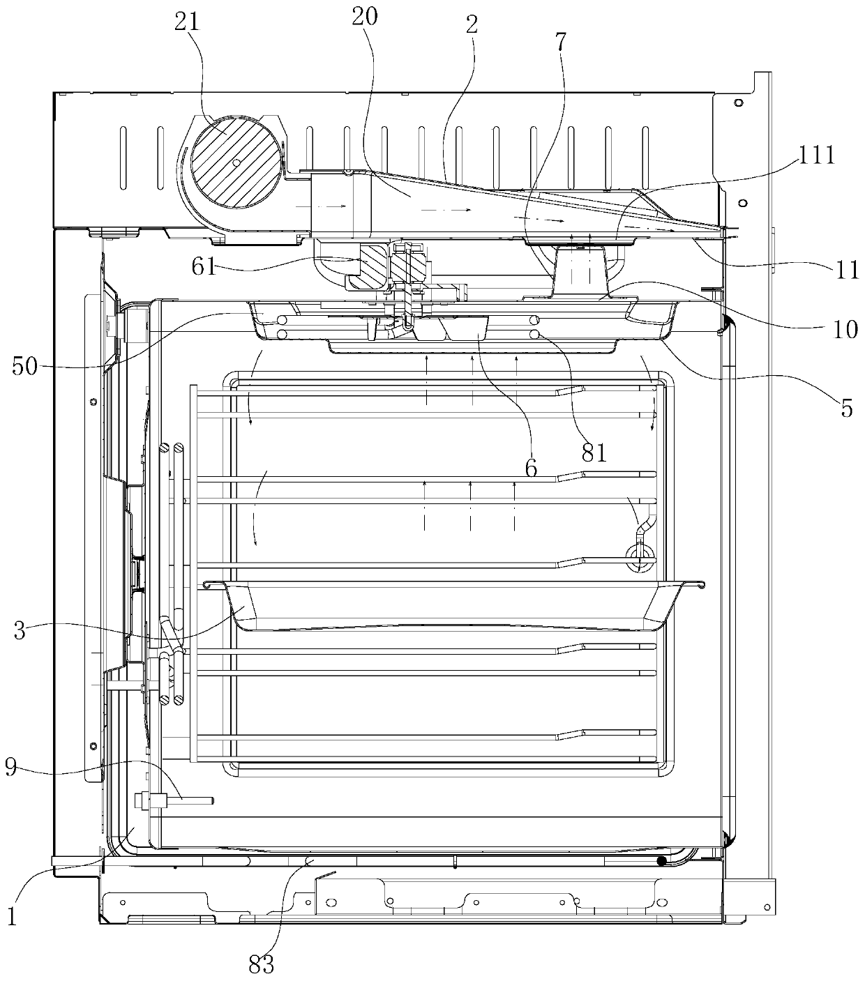
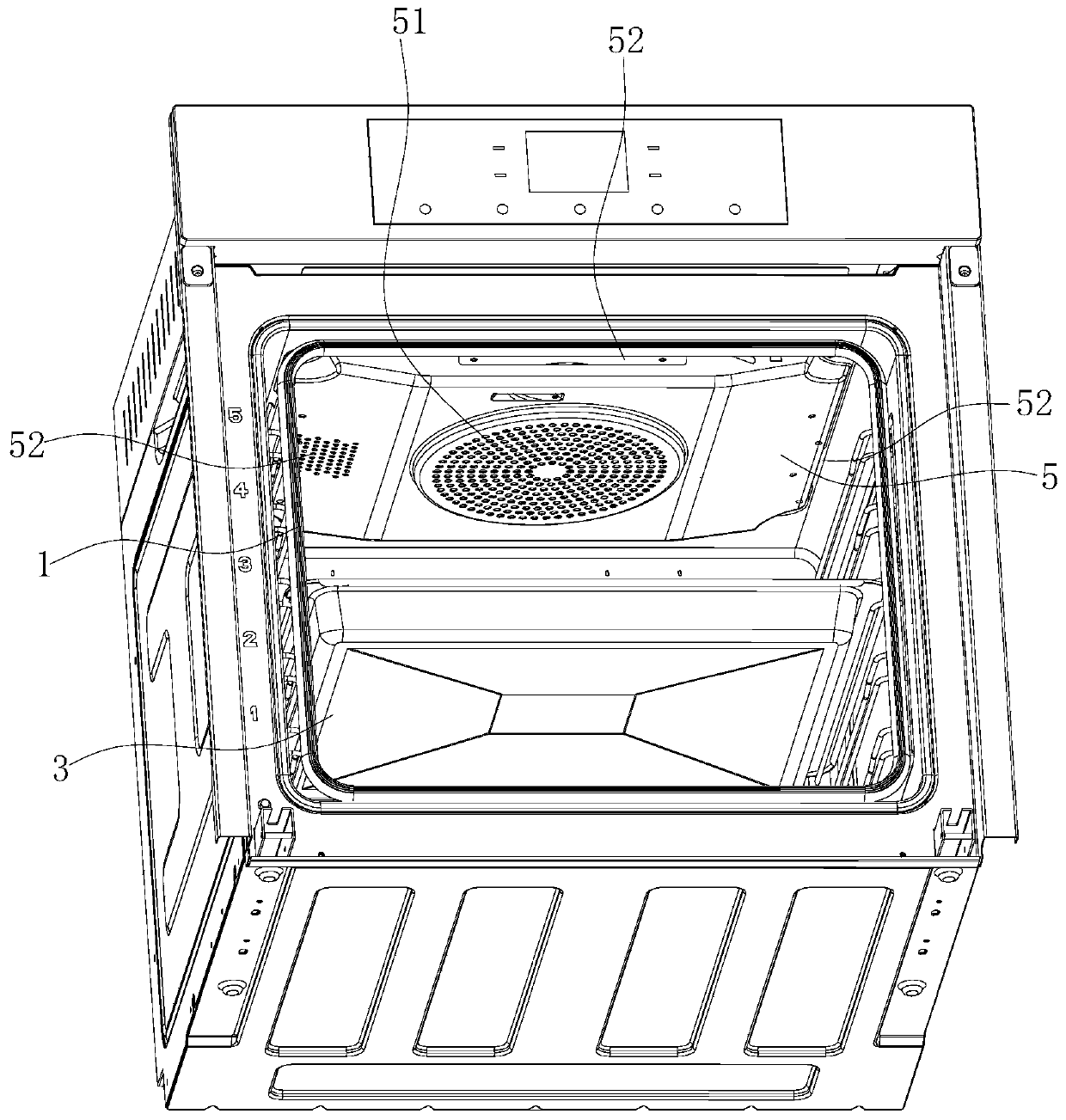
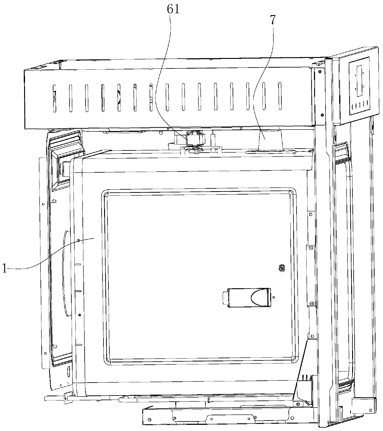
[0024] Such as Figure 1-7 As shown, a kind of oven with drying function includes an inner tank 1, an upper heating tube 81 is installed on the inner top surface of the inner tank 1, a lower heating tube 83 is installed on the bottom, and a back heating tube is installed on the inner surface of the back plate. Heating tube 82. An air outlet 10 is provided on the top wall of the inner container 1, and an upper mounting plate 11 is arranged above the inner container 1. The upper mounting plate 11 is covered with a wind guide cover 2, and the wind guide cover 2 is surrounded by the upper mounting plate 11. An exhaust channel 20 is formed, and the air inlet end of the exhaust channel 20 is provided with an exhaust fan 21, and the exhaust fan 21 is a cross-flow fan in this embodiment. An exhaust hole 111 is opened on the upper mounting plate 11, ...


PUM


Abstract

The invention relates to an oven with a drying function, which comprises an inner container, a baking tray is transversely arranged in the inner container, an exhaust port is formed in a top plate ofthe inner container and communicated with an exhaust passage with an exhaust fan through fluid, and the oven further includes a lifting device capable of driving the baking tray to reciprocate up anddown. Compared with the prior art, according to the invention, the baking tray can reciprocate up and down under the action of the lifting device; food to be dried placed on the baking tray shakes relative to the baking tray in the up-down reciprocating motion process of the baking tray. Meanwhile, in the working process of the oven, the exhaust fan rotates to form negative pressure in the exhaustpassage; hot air flow from bottom to top is formed in the inner container through the exhaust port, and food particles separated from the surface of the baking tray are completely exposed in the hotair flow to shake under the combined action of the hot air flow and the gravity of the food particles, so that heat exchange and water exchange are quickly performed, and food is quickly dried.

Description

technical field [0001] The invention relates to the field of ovens, in particular to an oven with a drying function. Background technique [0002] An oven is a common cooking device, which implements baking and grilling of food through a built-in heating device. The rear side of the liner of the oven is generally provided with a hot air baffle with an air inlet and an air outlet. The hot air baffle and the back plate of the inner container form a hot air chamber. A hot air blower is arranged in the hot air chamber. There is a back heating tube around the outside. When the hot air blower rotates, the air in the inner container is sucked into the hot air chamber through the air inlet on the hot air baffle, and the air sucked into the hot air chamber is heated into hot air and then flows back into the inner container through the air outlet on the hot air baffle. The hot air returned to the inner pot heats the food. Since the hot air baffle and the hot air blower are arranged...

Claims


Application Information

Patent Timeline
IPC IPC(8): A47J37/04A47J37/06
CPCA47J37/04A47J37/0641
Inventor 卜玲娟蒋圣伟
Owner NINGBO FOTILE KITCHEN WARE CO LTD
Why Eureka
Try Eureka