Steel bar bending system for building construction

A steel bar bending and building construction technology, applied in the field of steel bar bending system, can solve problems such as slippage, irregular shape, inaccurate steel bar bending angle, etc., and achieve the effect of weakening relative sliding, improving stability and increasing friction

Inactive Publication Date: 2020-01-17
徐甲
View PDF8 Cites 0 Cited by
  • Summary
  • Abstract
  • Description
  • Claims
  • Application Information

AI Technical Summary

Problems solved by technology

[0002] Steel bars are the most common workpieces in construction. The steel bars used in construction have ring marks on the surface. At present, the steel bar bending system uses molds with smooth surfaces. When using such molds for bending, and When bending in a vertical state, it is easy to slip, the bending angle of the steel bar is not accurate, and the shape is not standardized

Method used


Image

  • Steel bar bending system for building construction
  • Steel bar bending system for building construction
  • Steel bar bending system for building construction

Examples


Embodiment

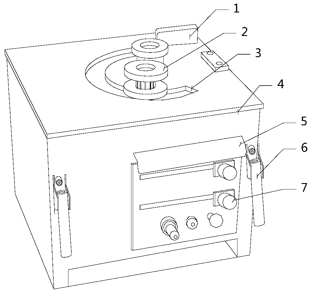
[0024] Please refer to Figure 1-Figure 5 , the present invention provides a steel bar bending system for building construction, the structure of which includes a fixed block 1, a mold 2, a groove 3, a body 4, a shutter 5, a fixed rod 6, and a control panel 7, and the top end of the body 4 faces A groove 3 is arranged in the middle, the groove 3 is an arc structure, a mold 2 is respectively installed at both ends of the arc of the groove 3, and a control panel 7 is installed on the front end of the body 4, and the control panel 7 A shroud 5 is arranged directly above, and the shroud 5 is welded to the body 4, and the control panel 7 is equipped with fixed rods 6 on both horizontal sides.

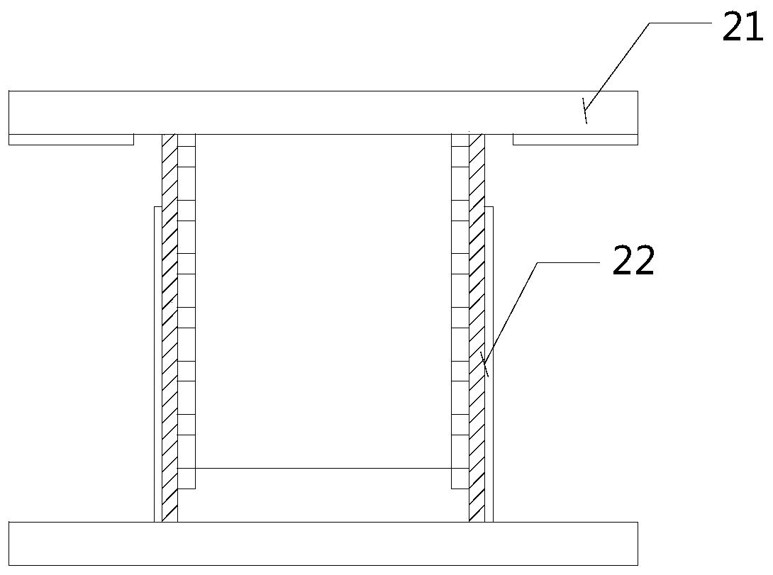
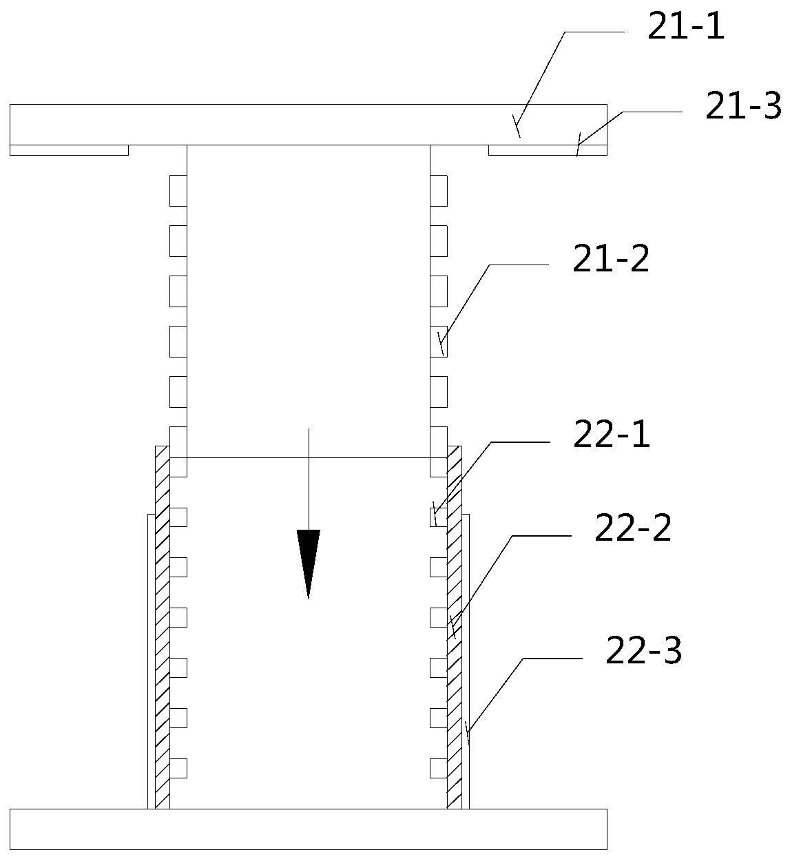
[0025] The mold 2 is provided with an adjustment inner cylinder 21 and a bottom cylinder 22, the bottom cylinder 22 is arranged on the body 4, the adjustment inner cylinder 21 has a "T" shape structure, and the bottom cylinder 22 is an inverted "T" shape Structure, the vertical end of the a...


PUM


Abstract

The invention discloses a steel bar bending system for building construction. The steel bar bending system for building construction structurally comprises a fixed block, dies, a groove, a machine body, a shielding plate, fixed rods and a control panel, wherein the groove is formed in the middle of the top end surface of the machine body; the groove is of an arc-shaped structure; one die is installed at the two ends of the arc shape of the groove separately; the control panel is installed on the front end surface of the machine body; the shielding plate is arranged above the control panel; theshielding plate is welded to the machine body; the fixed rods are installed at the two horizontal sides of the control panel; each die is provided with an inner adjustment barrel and a bottom barrel;each bottom barrel is arranged on the machine body; each inner adjustment barrel is of a T-shaped structure; each bottom barrel is of an inverted T-shaped structure; a vertical end of each inner adjustment barrel and a vertical end of the corresponding bottom barrel are movably matched to form an I-shaped structure; and steel bars are embedded into the I-shaped dies, and prevented from generatingfloating movement. According to the steel bar bending system for building construction, the vertical end of each inner adjustment barrel and the vertical end of the corresponding bottom barrel are movably matched to form the I-shaped structure; and the steel bars are embedded into the I-shaped dies, and prevented from generating floating movement.

Description

technical field [0001] The invention relates to the field of construction equipment, in particular to a steel bar bending system for building construction. Background technique [0002] Steel bars are the most common workpieces in construction. The steel bars used in construction have ring marks on the surface. At present, the steel bar bending system uses molds with smooth surfaces. When using such molds for bending, and When bending in a vertical state, it is easy to slip, the bending angle of the steel bar is not accurate, and the shape is not standardized. Contents of the invention [0003] Aiming at the deficiencies of the prior art, the present invention is realized through the following technical solutions: a steel bar bending system for building construction, the structure of which includes a fixed block, a mold, a groove, a body, a shroud, a fixed rod, and a control panel, A groove is provided in the middle of the top surface of the body, the groove is an arc str...

Claims


Application Information

Patent Timeline
Patent Type & Authority Applications(China)
IPC IPC(8): B21F1/00
CPCB21F1/00
Inventor 陶汉成
Owner 徐甲
Why Eureka
Try Eureka