Supporting mechanism and operating vehicle with same

A technology of support mechanism and support end, applied in vehicle maintenance, lifting vehicle accessories, transportation and packaging, etc., can solve the problems of cumbersome operation and complicated system, and achieve the effect of improving efficiency

Active Publication Date: 2020-01-17
CHANGSHA ZHONGLIAN HENGTONG MACHINERY
View PDF5 Cites 2 Cited by
  • Summary
  • Abstract
  • Description
  • Claims
  • Application Information

AI Technical Summary

Problems solved by technology

[0008] The purpose of the present invention is to overcome the system complexity and cumbersome operation caused by the use of two independent systems for the vehicle body supporting device and the body erecting device in the prior art, and to provide a single telescopic part to complete the swinging of the supporting legs and the body erecting device. Erect two-action supporting mechanism

Method used


Image

  • Supporting mechanism and operating vehicle with same
  • Supporting mechanism and operating vehicle with same
  • Supporting mechanism and operating vehicle with same

Examples


Embodiment 1

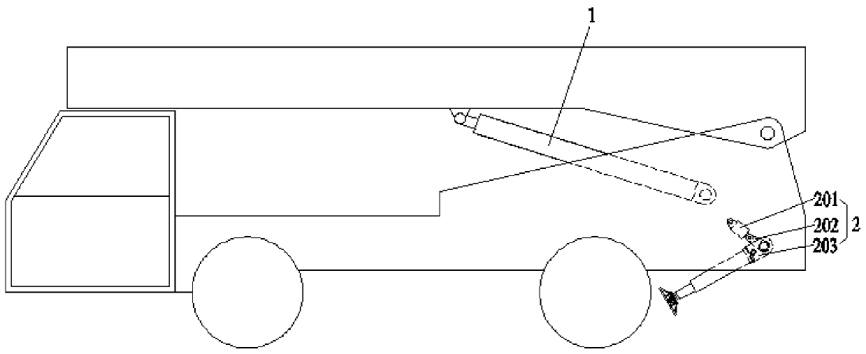
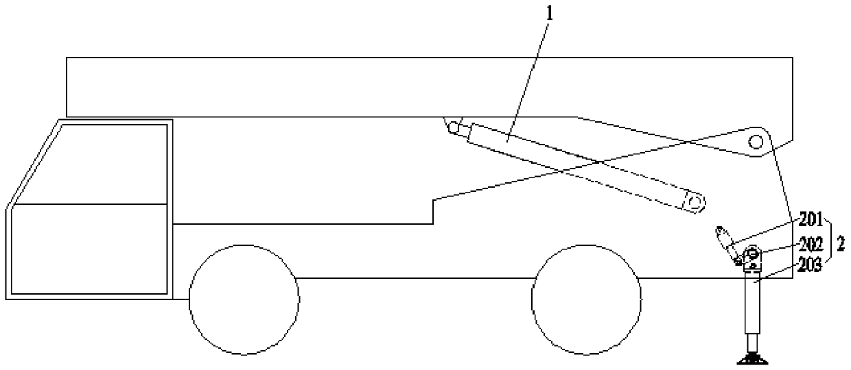
[0052] Such as figure 1 with figure 2 as shown, figure 1 It is a structural schematic diagram of the initial swing state of the support leg 203 of the existing support mechanism, figure 2 It is a structural schematic diagram of the state in which the support leg 203 of the existing support mechanism has been swiveled, from figure 1 with figure 2 It can be seen that the existing support mechanism is divided into two independent systems, one is the support of the car body, and the other is the erection of the top.

[0053] The vehicle body support device 2 is used to support the vehicle to prevent the vehicle from overturning when it is toppled. The support leg 203 is connected with the swing hydraulic cylinder 201 of the outrigger, and an intermediate link 202 is also arranged between the two. Driving the middle link 202 to rotate, the middle link 202 drives the support leg 203 fixedly connected to the middle link 202 to rotate, and the support leg 203 can support the ve...

Embodiment 2

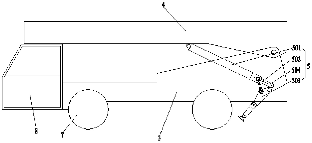
[0081] Such as image 3 with Figure 4 As shown, the work vehicle with the support mechanism is applied with the support mechanism described in Embodiment 1:

[0082] One end of the erecting telescopic member 501 is hinged with the top 4 of the vehicle, and the other end is hinged with one end of the connecting rod 502, and the other end of the connecting rod 502 is connected with the shaft or supporting end of the leg 503 , the end of the support leg 503 opposite to the support end is hinged to the frame 3, and the frame 3 and the bodywork 4 are hinged at the tails of both;

[0083] The support mechanism also includes a bar-shaped stop structure 504, and the range of movement of the hinge 505 connecting the erecting telescopic member 501 and the connecting rod 502 is limited by the bar-shaped stop structure 504 to control the legs 503 swing angle;

[0084] The hinge point between the erecting telescopic member 501 and the bodywork 4 can be set at the middle of the bodywork...


PUM


Abstract

The invention relates to the technical field of transportation loading and unloading, particularly relates to a supporting mechanism and an operating vehicle with the supporting mechanism. The supporting mechanism comprises a connecting rod mechanism, namely one end of an erecting telescopic piece is hinged with a loading part of a vehicle, the other end of the erecting telescopic piece is hingedwith one end of a connecting rod, the other end of the connecting rod is connected with a rod body or a supporting end of the supporting leg, and one end, opposite to the supporting end, of the supporting leg is hinged with a frame. During work, the erecting telescopic piece stretches out and draws back, the hinged end of the erecting telescopic piece and the connecting rod moves in a strip-shapedlimiting structure to drive the supporting leg to swing, the swing angle of the supporting leg is controlled by controlling the movement distance of the erecting telescopic piece and the connecting rod in the strip-shaped limiting structure, and the erecting telescopic piece drives the loading part to rotate and dump after swing is completed. The structure is used for replacing an independent supporting leg swinging and rotating system and an independent loading and erecting system, the control and operation are simplified, the supporting leg swinging and rotating process and the loading anderecting process are coherent, the operation conversion time is saved, and the problem that a traditional supporting mechanism is complex in control and manipulation is solved.

Description

technical field [0001] The invention relates to the field of transportation and loading and unloading technology, in particular to a support mechanism and a work vehicle with the support mechanism. Background technique [0002] The supporting mechanism of the existing transport vehicle includes two independent systems of body support and top loading erection. When dumping the load, it needs to be operated separately to complete the action of dumping the load. [0003] The independent bodywork erecting device is used for dumping the load. The bodywork hydraulic cylinder 1 is used to connect the frame 3 and the bodywork 4. When the bodywork hydraulic cylinder 1 stretches, the bodywork 4 rotates with the frame 3 as the fulcrum, thus completing the dumping of the load. . The independent car body supporting device 2 is used to support the vehicle to prevent the vehicle from overturning when it is toppled. The outrigger swing hydraulic cylinder 201 is used to connect the support ...

Claims


Application Information

Patent Timeline
Patent Type & Authority Applications(China)
IPC IPC(8): B60S9/10
CPCB60S9/10
Inventor 张虎刘龙兵徐驰宋院归
Owner CHANGSHA ZHONGLIAN HENGTONG MACHINERY
Why Eureka
Try Eureka