Free face transverse slip form concrete pouring device

A technology for pouring concrete and air-facing surfaces. It is applied in construction, erection/assembly of bridges, bridges, etc. It can solve the problems of increasing project cost, pouring concrete without bracket erection, increasing construction period, etc., and achieves the effect of continuous pouring

Inactive Publication Date: 2020-01-17
CHINA MCC17 GRP
View PDF7 Cites 0 Cited by
  • Summary
  • Abstract
  • Description
  • Claims
  • Application Information

AI Technical Summary

Problems solved by technology

[0002] At present, in the field of municipal engineering, more and more cities choose to use overpasses in congested areas to solve the problem of congestion and congestion on urban roads. However, during the construction of urban overpasses and bridges, the normal traffic flow must not be affected during the construction period. The conditions for erecting and pouring concrete for brackets, and the way of pouring concrete by lifting formwork by crane will inevitably increase the amount of crane shifts and increase the cost of the project, and the process of dismantling the formwork by crane is cumbersome and increases the construction period. Therefore, a new method is needed. The device can continue to move the formwork, so as to realize the purpose of pouring concrete on the empty surface

Method used


Image

  • Free face transverse slip form concrete pouring device
  • Free face transverse slip form concrete pouring device
  • Free face transverse slip form concrete pouring device

Examples


Embodiment 1

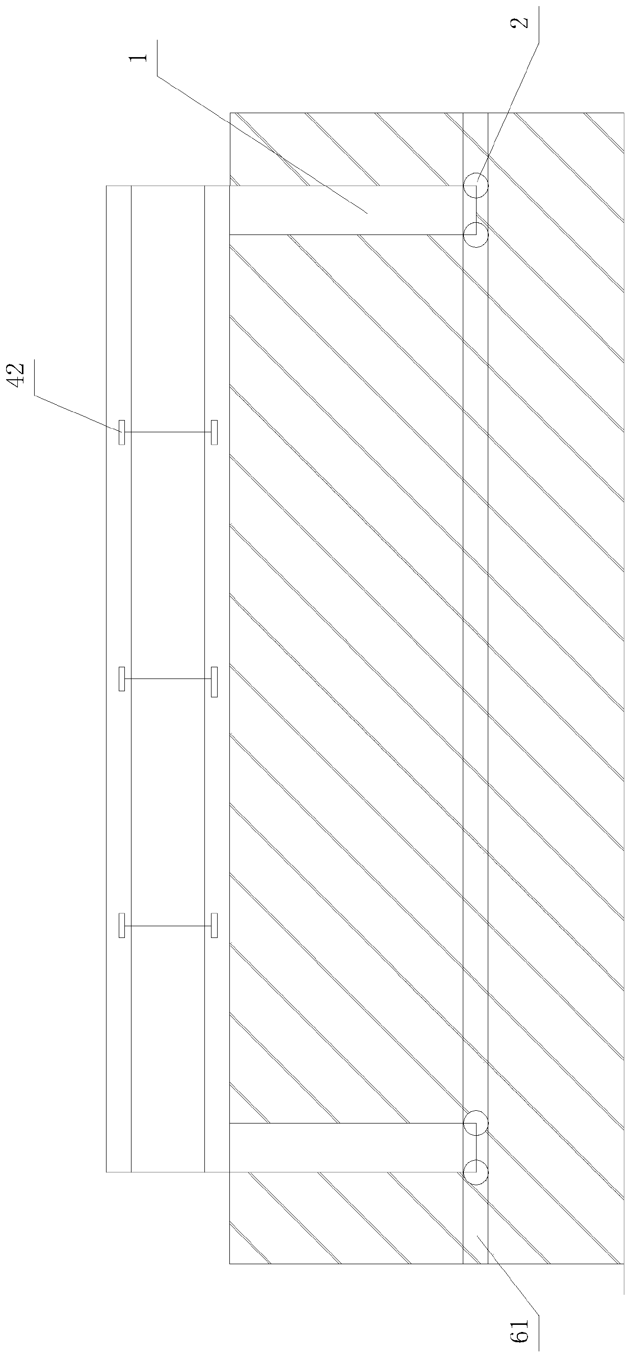
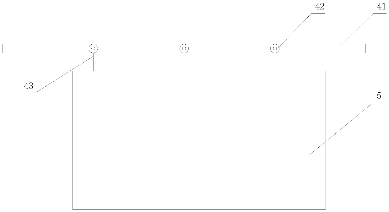
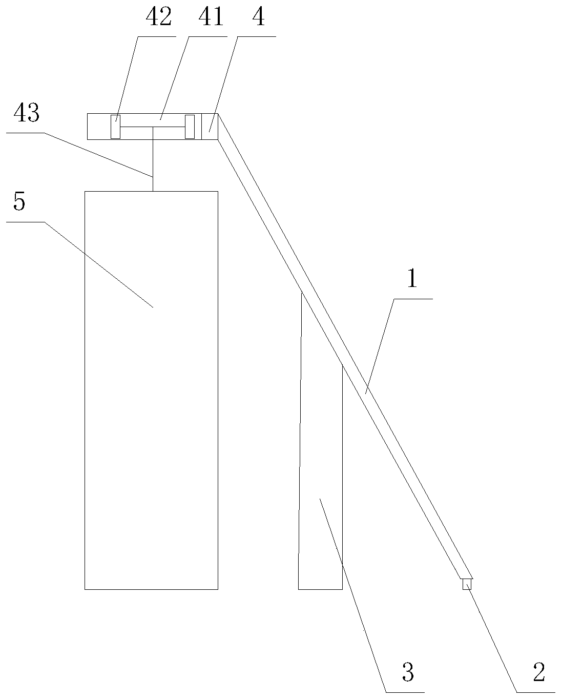
[0019] A device for pouring concrete with a horizontal sliding form on the air surface, comprising two fixing devices 1, the lower ends of the fixing devices 1 are fixedly connected with a first pulley 2, and the first pulley 2 moves on a first guide rail 61, and the The quantity of the first pulley 2 is 4, and each fixing device 1 is provided with 2 first pulleys 2, and the middle part of the fixing device 1 is connected with the steel box girder deck 3, and the upper end of the fixing device 1 is fixedly connected with Guide rail part 4, described guide rail part 4 is installed horizontally, and described guide rail part 4 is fixedly connected with second guide rail 41, and described second guide rail 41 is movably connected with 3 second pulleys 42, and the center of described second pulley 42 The shaft is fixedly connected with a bracket, and the bracket is fixedly connected with a steel rope 43 , and the lower end of the steel rope 43 is fixedly connected with a pin, and t...

Embodiment 2

[0022] The difference from Embodiment 1 is that there are six second pulleys (42).

Embodiment 3

[0024] The difference from Embodiment 1 is that there are four second pulleys (42).

[0025] It can be known that the technical effect of the technical solution adopted by the present invention is through the above-mentioned specific implementation manners: it has avoided the influence of the traditional construction technology on the normal traffic flow during the construction of the urban overpass bridge construction project; The method of pouring concrete by lifting the formwork by a crane results in high cost of mechanical shifts; this device is used in conjunction with the first pulley and the second pulley to complete the continuous pouring of concrete on the air surface, and the process of disassembling the formwork is simple. The construction period is short.


PUM


Abstract

The invention discloses a free face transverse slip form concrete pouring device including afixing device, the lower end of the fixing device is fixedly connected with a first pulley; the middle partof the fixing device is connected with a steel box girder bridge floor; a guide rail part is fixedly connected to the upper end of the fixing device, a guide rail is fixedly connected to the lower portion of the guide rail part, a second pulley is movably connected to the guide rail, a support is fixedly connected to a middle shaft of the second pulley, a steel rope is fixedly connected to the support, and a reinforced concrete formwork is fixedly connected to the lower end of the steel rope. According to the device, through cooperative use of the first pulley and the second pulley, continuouspouring work of free face concrete is completed, the formwork dismounting process is simple, and the construction period is short.

Description

technical field [0001] The patent of the present invention relates to the field of municipal engineering, in particular to a construction device for a reinforced concrete guardrail of a newly built upper-span bridge in a city. Background technique [0002] At present, in the field of municipal engineering, more and more cities choose to use overpasses in congested areas to solve the problem of congestion and congestion on urban roads. However, during the construction of urban overpasses and bridges, the normal traffic flow must not be affected during the construction period. The conditions for erecting and pouring concrete for brackets, and the way of pouring concrete by lifting formwork by crane will inevitably increase the amount of crane shifts and increase the cost of the project, and the process of dismantling the formwork by crane is cumbersome and increases the construction period. Therefore, a new method is needed. The device can continue to move the template, so as ...

Claims


Application Information

Patent Timeline
Patent Type & Authority Applications(China)
IPC IPC(8): E01D21/00
CPCE01D21/00
Inventor 王国栋
Owner CHINA MCC17 GRP
Why Eureka
Try Eureka