

Upper mould casting head device of signal connector mould device
A signal connector, mold casting technology, applied in the direction of coating, etc., can solve the problems of no casting mechanism and limited effect.
- Summary
- Abstract
- Description
- Claims
- Application Information
AI Technical Summary
Problems solved by technology
Method used
Image

Examples
Embodiment Construction
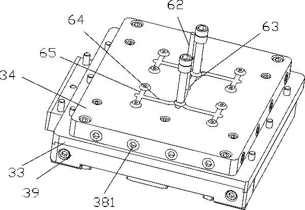
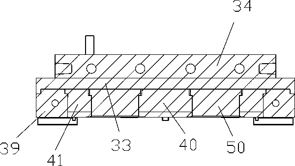
[0023] Examples, see e.g. Figures 1 to 5 As shown, an upper mold pouring head device of a signal connector mold device includes an upper main connection block 33, and an upper installation connection block 34 is fixed on the top surface of the upper main connection block 33;
[0024] A plurality of upper dies 50 are installed on the bottom surface of the upper main connecting block 33;
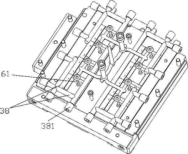
[0025] The installation groove on the upper installation connection block 34 is nested with a pouring main part 60, and the bottom end of the sub-casting pipe 61 of the pouring main part 60 protrudes from the bottom surface of the upper installation connection block 34 and the bottom surface of the upper main connection block 33 in turn. And insert sleeve in the pouring through hole 51 that just has in the middle part of patrix 50.
[0026] Further, the middle part of the bottom surface of the upper main connection block 33 is fixed with an upper middle connection support block 40, the left ...
PUM
 Abstract
Description
Claims
Application Information