Pin shaft locking structure

A technology of locking structure and pin shaft, applied in the field of machining

Pending Publication Date: 2020-01-17
JD DIGITS HAIYI INFORMATION TECHNOLOGY CO LTD
View PDF0 Cites 0 Cited by
  • Summary
  • Abstract
  • Description
  • Claims
  • Application Information

AI Technical Summary

Problems solved by technology

[0003] In view of this, the embodiment of the present invention provides a pin locking structure, which can solve the problem that the existing pin locking structure can only lock one component

Method used


Image

  • Pin shaft locking structure
  • Pin shaft locking structure
  • Pin shaft locking structure

Examples


Embodiment Construction

[0034] Exemplary embodiments of the present invention are described below in conjunction with the accompanying drawings, which include various details of the embodiments of the present invention to facilitate understanding, and they should be regarded as exemplary only. Accordingly, those of ordinary skill in the art will recognize that various changes and modifications of the embodiments described herein can be made without departing from the scope and spirit of the invention. Also, descriptions of well-known functions and constructions are omitted in the following description for clarity and conciseness.

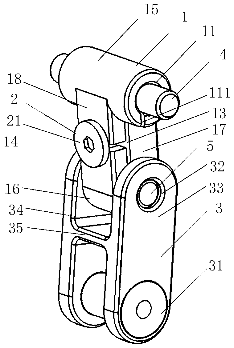
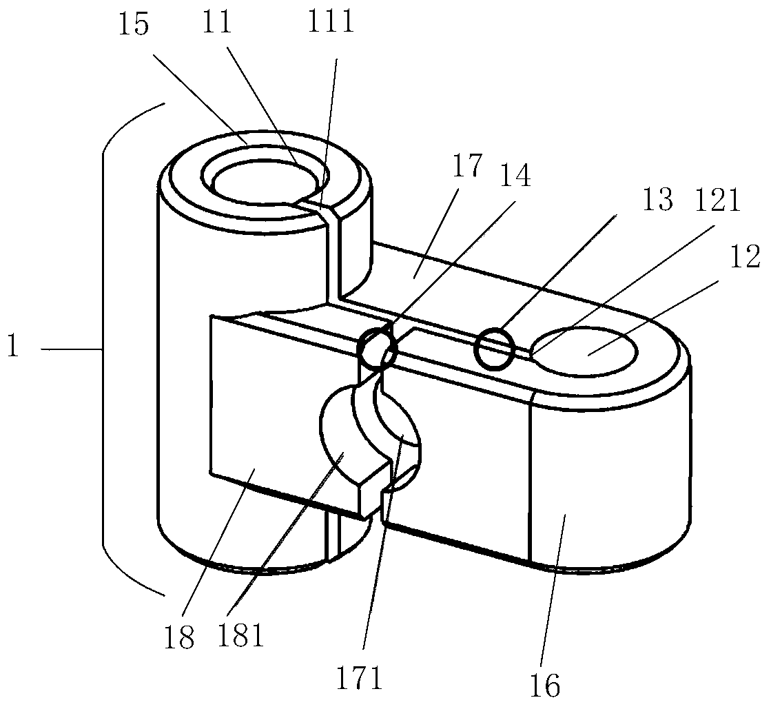
[0035] figure 1 with figure 2 is a structural schematic diagram of the pin shaft locking structure of the embodiment of the present invention, see figure 1 with figure 2 , the pin locking structure includes:

[0036] Mounting part 1, described mounting part 1 is provided with the first through hole 11 and the second through hole 12 that are used to install pin shaft,...


PUM


Abstract

The invention provides a pin shaft locking structure. The pin shaft locking structure includes a mounting component and a locking component. The mounting component is provided with a first through hole and a second through hole. The first through hole and the second through hole are provided with a first notch and a second notch correspondingly. A first slot is arranged between the first through hole and the second through hole. The first slot, the first notch and the second notch run through the mounting component and intercommunicate. One end of the locking component is detachably connectedwith the mounting component through the first slotting. When the mounting component is compressed by the other end of the locking component, the gap of the first slot is reduced to enable the gap between the first notch and the second notch to be reduced. The circumferential size of the first through hole and the second through hole diminishes, so pin shafts arranged between the first through holeand the second through hole can be locked, and the problem can be solved that an existing pin shaft locking structure can only lock one part.

Description

technical field [0001] The invention relates to the field of machining, in particular to a pin shaft locking structure. Background technique [0002] Generally, the existing pin locking structure can only lock one part. If multiple parts need to be locked, multiple existing pin locking structures are required to lock each part separately. The form can create a large number of redundant parts, which in turn increases the cost of the project. Contents of the invention [0003] In view of this, the embodiment of the present invention provides a pin locking structure, which can solve the problem that the existing pin locking structure can only lock one component. [0004] To achieve the above object, according to one aspect of the present invention, a pin locking structure is provided. [0005] A pin locking structure according to an embodiment of the present invention includes: [0006] A mounting part, the mounting part is provided with a first through hole and a second t...

Claims


Application Information

Patent Timeline
IPC IPC(8): F16B1/02
CPCF16B1/02
Inventor 程二亭韩久琦
Owner JD DIGITS HAIYI INFORMATION TECHNOLOGY CO LTD
Why Eureka
Try Eureka