Double-stator and barrel-type permanent magnet rotor accelerator with closed cycle multi-channel counterflow cooling

A counter-current cooling, closed-cycle technology, applied in magnetic circuit rotating parts, cooling/ventilation devices, magnetic circuit shape/style/structure, etc. question

Inactive Publication Date: 2019-03-29
HARBIN UNIV OF SCI & TECH
View PDF5 Cites 0 Cited by
  • Summary
  • Abstract
  • Description
  • Claims
  • Application Information

AI Technical Summary

Problems solved by technology

For the electromagnetic acceleration device with double stator structure, on the one hand, the inner stator has a smaller circumferential dimension than the outer stator, and the inner stator wire compound is higher, which makes the side of the inner stator generate serious heat; on the other hand, for the electromagnetic device with inner-outer double stator structure, The inner stator is built in the innermost part of the outer stator and rotor, and the inner stator cannot directly exchange heat with the external environment

Method used


Image

  • Double-stator and barrel-type permanent magnet rotor accelerator with closed cycle multi-channel counterflow cooling
  • Double-stator and barrel-type permanent magnet rotor accelerator with closed cycle multi-channel counterflow cooling

Examples


Embodiment

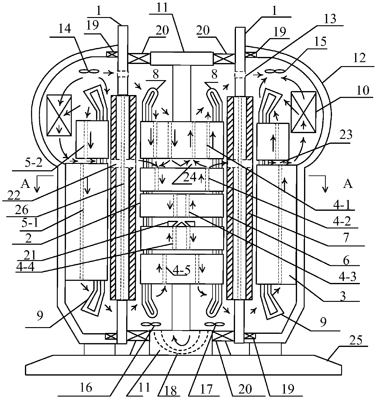
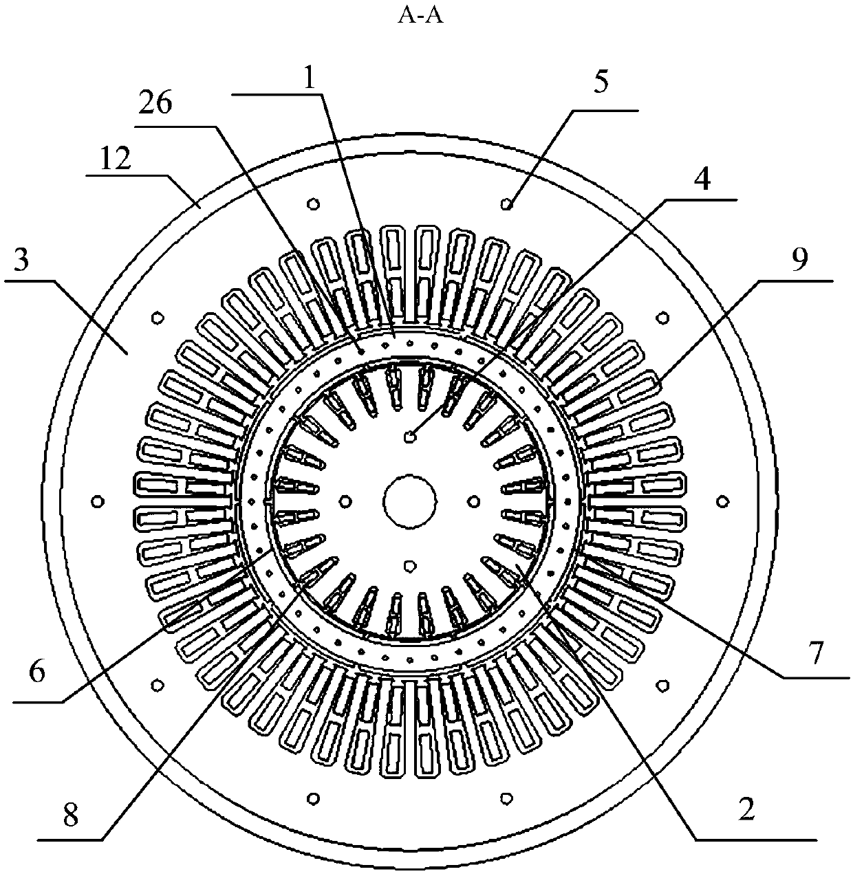
[0029] Example: see Figure 1 to Figure 2 , the dual-stator and cylindrical permanent magnet rotor accelerator with closed cycle multi-channel countercurrent cooling in this embodiment includes a cylindrical rotor 1, an inner stator core 2, an outer stator core 3, a permanent magnet 6 in the inner layer of the rotor, and an outer layer of the rotor Permanent magnet 7, inner stator winding 8, outer stator winding 9, inner stator casing 11, outer stator casing 12, cylindrical rotor outer ring bearing 19, cylindrical rotor inner ring bearing 20;

[0030]The cylindrical rotor 1 is arranged between the inner stator core 2 and the outer stator core 3, and the cylindrical rotor 1 is connected to the outer stator casing 12 and the outer stator casing 12 through the cylindrical rotor outer ring bearing 19 and the cylindrical rotor inner ring bearing 20 respectively. The inner stator casing 11 is connected, and the inner layer and the outer layer of the cylindrical rotor 1 are respectiv...


PUM


Abstract

The invention relates to a double-stator cylindrical permanent magnet rotor accelerator with closed circulation multi-channel counter flow cooling, and belongs to the technical field of electrical engineering. The invention needs to solve a technical problem of improving the power density of the accelerator, obtaining higher electromagnetic torque density and enhance the system response of the accelerator. The scheme is that an inner stator structure is further set in a rotor, both the inner and outer surfaces of the rotor are provided with surface-mounted permanent magnets, and windings of the inner and outer stators are simultaneously supplied with high frequency electricity. The double stator and cylindrical permanent magnet rotor structure improves the power density of the acceleratorand obtains higher electromagnetic torque density, and has the characteristics of small rotational inertia and fast system response at the same time. The forced multi-channel circulation closed counter flow cooling mode of the accelerator improves the cooling efficiency of the accelerator, reduces the temperature rise of the system under high-speed rotation and ensures the stable operation of thesystem under high-frequency power supply acceleration of the accelerator. In addition, the accelerator is less disturbed by external factors due to adoption of the closed structure, thereby being applicable for immersion in a fuel liquid, and not affecting the cooling system.

Description

technical field [0001] The invention relates to a rotor accelerator with a cooling system, in particular to a dual-stator and barrel-type permanent magnet rotor accelerator with closed cycle multi-channel countercurrent cooling, belonging to the technical field of electrical engineering. Background technique [0002] The manufacture of high-tech products has extremely high requirements on system performance and heat generation limit, especially some electromagnetic precision devices used in the aerospace field, which require excellent stability, accuracy, rapidity, robustness, etc. , while showing superior performance, its effective heat dissipation is also a key issue, which is one of the core design technologies. [0003] When the rotor of the accelerator rotates at high speed, if the cooling effect of the inner stator is not good, it will cause the accelerator to burn out, and even endanger the safe operation of the entire system. Therefore, it is necessary to design an ...

Claims


Application Information

Patent Timeline
Patent Type & Authority Patents(China)
IPC IPC(8): H02K16/04H02K1/16H02K1/27H02K1/20H02K9/06
CPCH02K1/165H02K1/20H02K1/27H02K9/06H02K16/04
Inventor 王立坤寇宝泉张赫周一恒郭庆波
Owner HARBIN UNIV OF SCI & TECH
Why Eureka
Try Eureka