
Underwater pressure-equalizing exhaust emission experiment device

An experimental device and launch tube technology, applied in the field of underwater testing, can solve problems such as insufficient pressure in the cavity, complicated operation, and difficult air cavity, and achieve the effects of stable posture, large internal space, and expanded filling space

Active Publication Date: 2020-01-17
HARBIN INST OF TECH AT WEIHAI
View PDF7 Cites 4 Cited by
  • Summary
  • Abstract
  • Description
  • Claims
  • Application Information

AI Technical Summary

Problems solved by technology

Due to the lack of experimental devices for underwater equal-pressure exhaust emission and the given trajectory of the vehicle, it is difficult to realize the free exhaust movement, which makes it difficult to study its free exhaust movement. The internal air cavity is small, and the pressure in the cavity is insufficient; while the vehicle is launched, it is difficult to realize the automatic synchronous trigger design of the air cavity, so as to balance the changes in internal and external pressure differences in time; in addition, the trigger mechanism for underwater launch experiments is poor in water resistance , operating complex issues

Method used


Image

  • Underwater pressure-equalizing exhaust emission experiment device
  • Underwater pressure-equalizing exhaust emission experiment device
  • Underwater pressure-equalizing exhaust emission experiment device

Examples


specific Embodiment approach 1

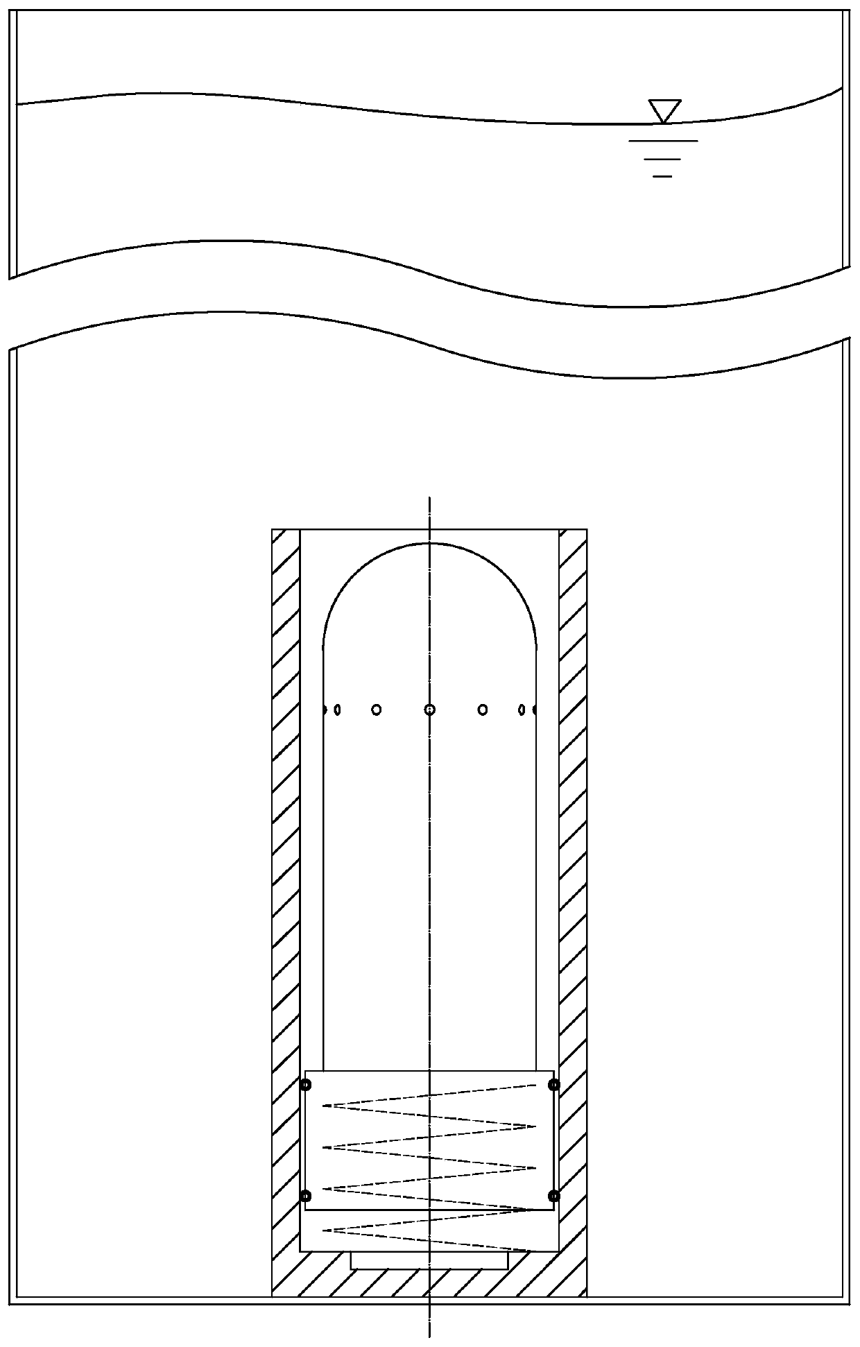
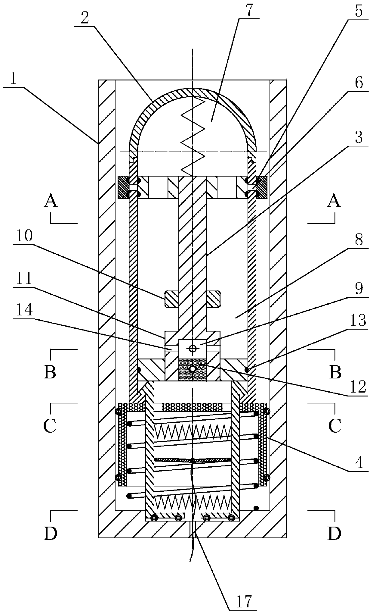
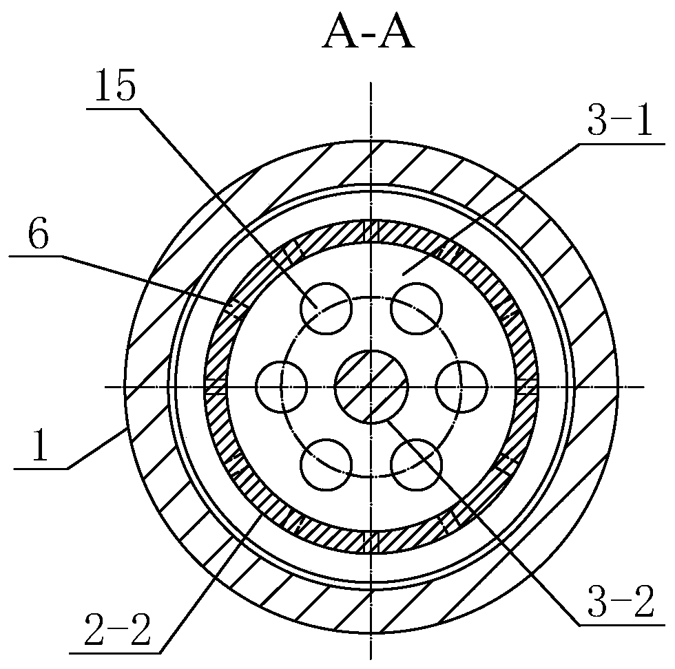
[0037] Specific implementation mode one: combine figure 1 , figure 2 , image 3 , Figure 4 , Figure 5 , Figure 6 , Figure 7 , Figure 8 , Figure 9 and Figure 10Describe this embodiment. This embodiment includes a launch tube 1, a navigation body 2, a double-headed piston 3, a pusher 4 and a sealing ring 5, and the navigation body 2 and the pusher 4 are sequentially arranged in the launch tube 1 from top to bottom. , the navigation body 2 makes the action of ejecting the launch tube 1 under the push of the pusher 4, the navigation body 2 includes a head cover 2-1 and a column body 2-2, and the head cover 2-1 is detachably connected to the body of the column body 2-2. The top, the top of the column body 2-2 is processed with an exhaust hole 6 along its circumferential direction, the bottom of the column body 2-2 is provided with a first bottom hole 2-3, and the double-headed piston 3 is vertically arranged on the column body 2-2. Inside, the upper end of the doub...

specific Embodiment approach 2

[0042] Embodiment 2: This embodiment is a further limitation of Embodiment 1. The double-headed piston 3 includes an upper plug head 3-1, a plug rod 3-2 and a lower plug head 3-3. The upper plug head 3-1, the plug The rod 3-2 and the lower plug head 3-3 are sequentially arranged in the navigation body 2 from top to bottom, and the two ends of the plug rod 3-2 are respectively fixedly connected with the upper plug head 3-1 and the lower plug head 3-3, and the head The cover 2-1 and the upper plug head 3-1 enclose to form the main air chamber 7, and the upper plug head 3-1, the lower plug head 3-3 and the inner wall of the column body 2-2 enclose to form the secondary air chamber 8. The main air chamber 7 communicates with the auxiliary air chamber 8 .

specific Embodiment approach 3

[0043] Specific embodiment three: this embodiment is a further limitation of specific embodiment two, the lower end of the plug rod 3-2 is provided with a connector 11, the connector 11 is fixedly fitted with a lower plug 3-3, and the connector 11 is processed with a The cavity 9 is processed with a first air hole 14 communicating with the auxiliary air cavity 8 on the side wall of the cavity 9 , and the bottom of the connector 11 is provided with a one-way valve 12 communicating with the cavity.

[0044] Further, the shapes of the upper plug head 3-1 and the lower plug head 3-3 are disc-shaped, and the upper plug head 3-1 is processed with a plurality of second vent holes 15 along its circumferential direction, and the main air cavity 7 passes through multiple air holes. A second vent hole 15 communicates with the secondary air chamber 8. The connecting head 11 is processed with a plurality of first air holes 14 along its circumferential direction, and the auxiliary air cavit...


PUM


Abstract

The invention discloses an underwater pressure-equalizing exhaust emission experiment device. In the underwater pressure-equalizing exhaust emission experiment device, the situation that the free exhaust motion of a navigation body is difficult to study due to the given motion track of the navigation body is avoided. According to the underwater pressure-equalizing exhaust emission experiment device, the navigation body and a pusher are sequentially arranged in an emission cylinder from top to bottom, the navigation body is pushed by the pusher to make the action of emitting out of the emissioncylinder, the navigation body comprises a head cover and a cylinder body, the head cover is detachably connected to the top of the cylinder body, an exhaust hole is machined in the top of the cylinder body in the circumferential direction of the cylinder body, a first bottom hole is formed in the bottom of the cylinder body, a double-head piston is vertically arranged in the cylinder body, the upper end of the double-head piston is tightly attached to the exhaust hole, the lower end of the double-head piston is arranged at the bottom of the cylinder body, and a sealing ring is arranged outside the exhaust hole of the cylinder body in a sleeving mode. The underwater pressure-equalizing exhaust emission experiment device is used for underwater emission experiments of the navigation body.

Description

technical field [0001] The invention belongs to the technical field of underwater testing, and in particular relates to an underwater pressure-equalizing exhaust launching experiment device. Background technique [0002] Submarine-launched weapons occupy a very important position in the marine combat system. Underwater launch technology is the core technology of the submarine-launched weapon system. The launch of submarine-launched missiles includes three important stages: the launch of the vehicle, navigation in the water, and crossing the water surface. There are many factors affecting the whole process, and the force of the vehicle changes drastically. Although it is only a few seconds, it has a decisive influence on the attitude of the vehicle after it emerges from the water, which is related to the success or failure of the underwater launch of the submarine-launched vehicle. [0003] The underwater movement speed of the vehicle body is relatively high, and the pressure...

Claims


Application Information

Patent Timeline
Patent Type & Authority Applications(China)
IPC IPC(8): F41F1/00
CPCF41F1/00
Inventor 王威何广华罗婷婷罗念宁
Owner HARBIN INST OF TECH AT WEIHAI
Learn More