Strong electromagnetic pulse shielding effectiveness test system and method

A shielding effectiveness and testing system technology, applied in the fields of electromagnetic field characteristics, measuring devices, measuring electrical variables, etc., can solve problems such as difficult to meet the testing requirements of shielding materials, achieve improved dynamic range, make up for measurement errors, high accuracy and reliability degree of effect

Active Publication Date: 2020-01-17
INST OF APPLIED ELECTRONICS CHINA ACAD OF ENG PHYSICS
View PDF10 Cites 20 Cited by
  • Summary
  • Abstract
  • Description
  • Claims
  • Application Information

AI Technical Summary

Problems solved by technology

[0004] The purpose of the present invention is to solve the current situation that the traditional shielding effectiveness test method is difficult to meet the test requirements of shielding materials under the condition of strong electromagnetic pulse, and propose a strong electromagnetic pulse shielding effectiveness test system and method with high accuracy, large dynamic range and easy operation

Method used


Image

  • Strong electromagnetic pulse shielding effectiveness test system and method
  • Strong electromagnetic pulse shielding effectiveness test system and method
  • Strong electromagnetic pulse shielding effectiveness test system and method

Examples


Embodiment 1

[0051] Such as figure 1 with figure 2 As shown, a strong electromagnetic pulse shielding effectiveness test system includes a strong electromagnetic pulse source, a test shielding cavity, a pulse field signal receiving circuit and a pulse field signal compensation circuit; the test shielding cavity is a cubic structure sealed cavity, which is made of cold-rolled steel plate Manufactured, the length, width and height are 1.5m, and the absorbing material is attached inside the cavity to eliminate the influence of resonance on the test. A test window of 300mm×300mm is opened on one side of the shielding chamber for placing the tested samples. The test shielding chamber is placed on a movable and height-adjustable mobile bracket, which is easy to adjust to meet the test requirements of different strong electromagnetic pulse sources.

[0052] The strong electromagnetic pulse source generates a strong electromagnetic pulse field in the microwave anechoic chamber; the test shieldi...

Embodiment 2

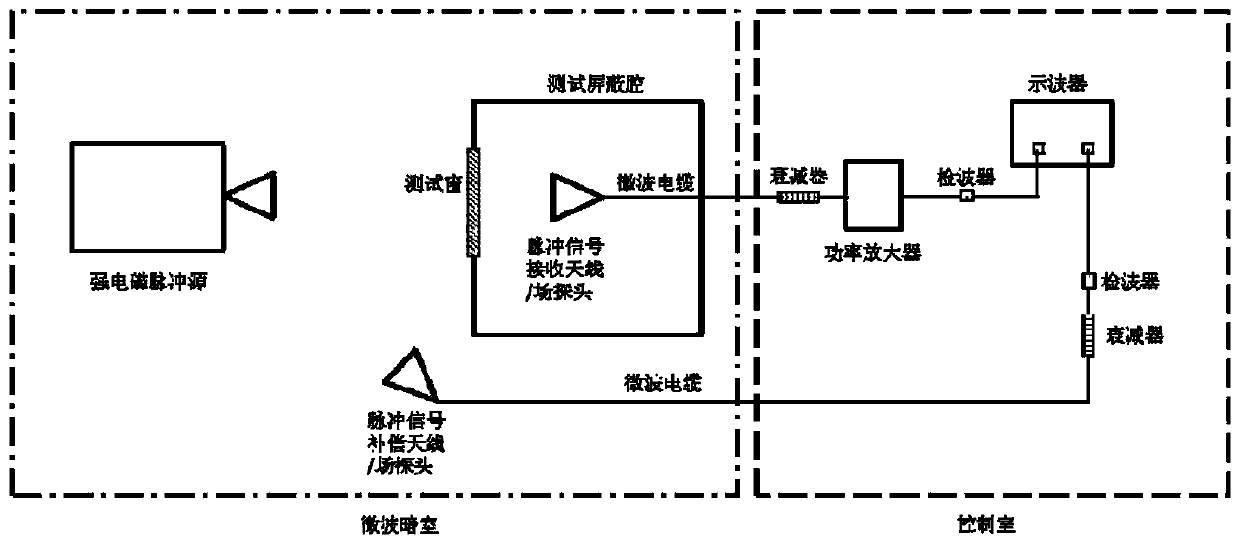
[0066] A method for testing the strong electromagnetic pulse shielding effectiveness of electromagnetic shielding materials using the aforementioned strong electromagnetic pulse shielding effectiveness test system, the pulse field signal receiving loop and the pulse field signal compensation loop are microwave loops, and the test method includes the following steps:

[0067] Step 1. Calibrate the attenuation value of the microwave cable and the attenuator, and calibrate the sensitivity of the detector;

[0068] Step 2. According to the test requirements, calibrate the strong electromagnetic pulse field, specify the test location, and record the parameter configuration of the strong electromagnetic pulse source;

[0069] Step 3. Place the test shielding cavity at the field strength calibration point, and at the same time place the pulse signal compensation antenna on one side of the test shielding cavity and fix the position; set up the pulse signal compensation antenna at the f...

Embodiment 3

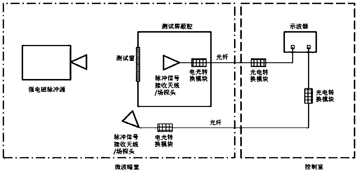
[0077] A method for testing the strong electromagnetic pulse shielding effectiveness of electromagnetic shielding materials using the aforementioned strong electromagnetic pulse shielding effectiveness test system, the pulse field signal receiving loop and the pulse field signal compensation loop are optical fiber loops; the test method includes the following steps:

[0078] Step 1. Calibrate the sensitivity of the optical fiber loop (receiving antenna / field probe-first electro-optical conversion module-first photoelectric conversion module; compensation antenna / field probe-second electro-optical conversion module-second photoelectric conversion module);

[0079] Step 2. According to the test requirements, calibrate the strong electromagnetic pulse field, specify the test location, and record the parameter configuration of the strong electromagnetic pulse source;

[0080] Step 3. Place the test shielding cavity at the field strength calibration point, and at the same time place...


PUM


Abstract

The invention discloses a strong electromagnetic pulse shielding effectiveness test system which comprises a strong electromagnetic pulse source, a test shielding cavity, a pulse field signal receiving loop and a pulse field signal compensation loop; the strong electromagnetic pulse source generates a strong electromagnetic pulse field in an anechoic chamber, a test window is formed in the side surface of the test shielding cavity, the shielding cavity is arranged in the anechoic chamber, and the side with the test window of the shielding cavity faces the incoming wave direction; each of the pulse field signal receiving loop and the pulse field signal compensation loop comprise receiving antenna / field probes, signal transmission loops and a signal display device; and each receiving antenna / field probe is connected with the signal display device through the first signal transmission loop or the second signal transmission loop. In addition, the invention further discloses a method corresponding to the system. Blanks in the field of strong electromagnetic pulse shielding effectiveness test system and the method are filled. The system is wide in the dynamic range, and a test result isextremely high in accuracy.

Description

technical field [0001] The invention belongs to the technical field of shielding effectiveness testing of electromagnetic shielding materials, and in particular relates to a strong electromagnetic pulse shielding effectiveness testing system and method. Background technique [0002] Shielding effectiveness is one of the most important properties of electromagnetic shielding materials. Accurate testing and characterization of shielding effectiveness is crucial to the practical application of shielding materials, especially with the emergence of strong electromagnetic pulse threats such as high-power microwaves and nuclear electromagnetic pulses in recent years. , has created a greater threat to the normal work of electronic equipment, and there is an urgent need for strong electromagnetic pulse protection for electronic equipment. Therefore, accurate characterization and testing of the shielding effectiveness of shielding materials under strong electromagnetic pulse condition...

Claims


Application Information

Patent Timeline
Patent Type & Authority Applications(China)
IPC IPC(8): G01R29/08
CPCG01R29/0814
Inventor 严志洋秦风高原林江川蔡金良钟受洪范均赵刚马弘舸
Owner INST OF APPLIED ELECTRONICS CHINA ACAD OF ENG PHYSICS
Why Eureka
Try Eureka