A strong electromagnetic pulse shielding effectiveness test system and method
A shielding effectiveness and testing system technology, applied in the fields of electromagnetic field characteristics, measuring devices, and measuring electrical variables, can solve problems such as difficult to meet the testing requirements of shielding materials, achieve improved dynamic range, high accuracy and reliability, and make up for measurement wrong effect
- Summary
- Abstract
- Description
- Claims
- Application Information
AI Technical Summary
Problems solved by technology
Method used
Image
Examples
Embodiment 1
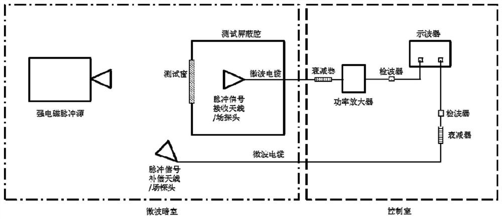
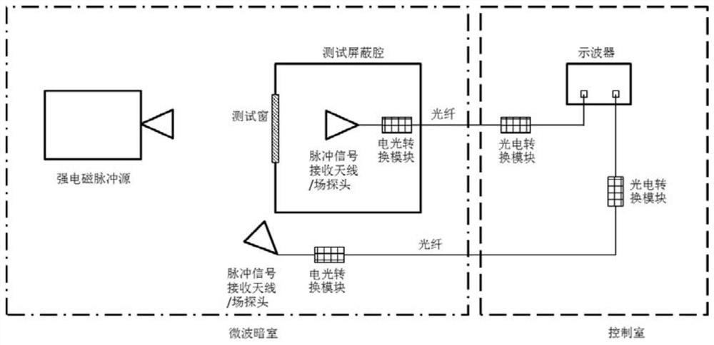
[0051] Such as figure 1 with figure 2 As shown, a strong electromagnetic pulse shielding effectiveness test system includes a strong electromagnetic pulse source, a test shielding cavity, a pulse field signal receiving circuit and a pulse field signal compensation circuit; the test shielding cavity is a cubic structure sealed cavity, which is made of cold-rolled steel plate Manufactured, the length, width and height are 1.5m, and the absorbing material is attached inside the cavity to eliminate the influence of resonance on the test. A test window of 300mm×300mm is opened on one side of the shielding chamber for placing the tested samples. The test shielding chamber is placed on a movable and height-adjustable mobile bracket, which is easy to adjust to meet the test requirements of different strong electromagnetic pulse sources.
[0052] The strong electromagnetic pulse source generates a strong electromagnetic pulse field in the microwave anechoic chamber; the test shieldi...
Embodiment 2
[0066] A method for testing the strong electromagnetic pulse shielding effectiveness of electromagnetic shielding materials using the aforementioned strong electromagnetic pulse shielding effectiveness test system, the pulse field signal receiving loop and the pulse field signal compensation loop are microwave loops, and the test method includes the following steps:
[0067] Step 1. Calibrate the attenuation value of the microwave cable and the attenuator, and calibrate the sensitivity of the detector;
[0068] Step 2. According to the test requirements, calibrate the strong electromagnetic pulse field, specify the test location, and record the parameter configuration of the strong electromagnetic pulse source;
[0069] Step 3. Place the test shielding cavity at the field strength calibration point, and at the same time place the pulse signal compensation antenna on one side of the test shielding cavity and fix the position; set up the pulse signal compensation antenna at the f...
Embodiment 3
[0077] A method for testing the strong electromagnetic pulse shielding effectiveness of electromagnetic shielding materials using the aforementioned strong electromagnetic pulse shielding effectiveness test system, the pulse field signal receiving loop and the pulse field signal compensation loop are optical fiber loops; the test method includes the following steps:
[0078] Step 1. Calibrate the sensitivity of the optical fiber loop (receiving antenna / field probe-first electro-optical conversion module-first photoelectric conversion module; compensation antenna / field probe-second electro-optical conversion module-second photoelectric conversion module);
[0079] Step 2. According to the test requirements, calibrate the strong electromagnetic pulse field, specify the test location, and record the parameter configuration of the strong electromagnetic pulse source;
[0080] Step 3. Place the test shielding cavity at the field strength calibration point, and at the same time place...
PUM
 Abstract
Description
Claims
Application Information
 - R&D
- Intellectual Property
- Life Sciences
- Materials
- Tech Scout
- Unparalleled Data Quality
- Higher Quality Content
- 60% Fewer Hallucinations
Browse by: Latest US Patents, China's latest patents, Technical Efficacy Thesaurus, Application Domain, Technology Topic, Popular Technical Reports.
© 2025 PatSnap. All rights reserved.Legal|Privacy policy|Modern Slavery Act Transparency Statement|Sitemap|About US| Contact US: help@patsnap.com


