Supercharge Your Innovation With Domain-Expert AI Agents!

Method for monitoring an operating state of a pumping device

A pumping device, operating state technology, applied in the direction of pump combinations, pumps, pump elements, etc. for elastic fluid rotary piston type/oscillating piston type

Active Publication Date: 2020-01-17
PFEIFFER VACUUM GMBH
View PDF6 Cites 1 Cited by
  • Summary
  • Abstract
  • Description
  • Claims
  • Application Information

AI Technical Summary

Problems solved by technology

Moreover, modification of process conditions then requires modification of the model used by the analysis system, which is not a simple process during the use of vacuum pumps

Method used


Image

  • Method for monitoring an operating state of a pumping device
  • Method for monitoring an operating state of a pumping device
  • Method for monitoring an operating state of a pumping device

Examples


Embodiment Construction

[0041] The following embodiments are examples. Although the description refers to one or more embodiments, this does not necessarily mean that every talk is about the same embodiment, or that these features are only applicable to one embodiment. Single features of different embodiments may be equivalently combined or interchanged to provide other embodiments.

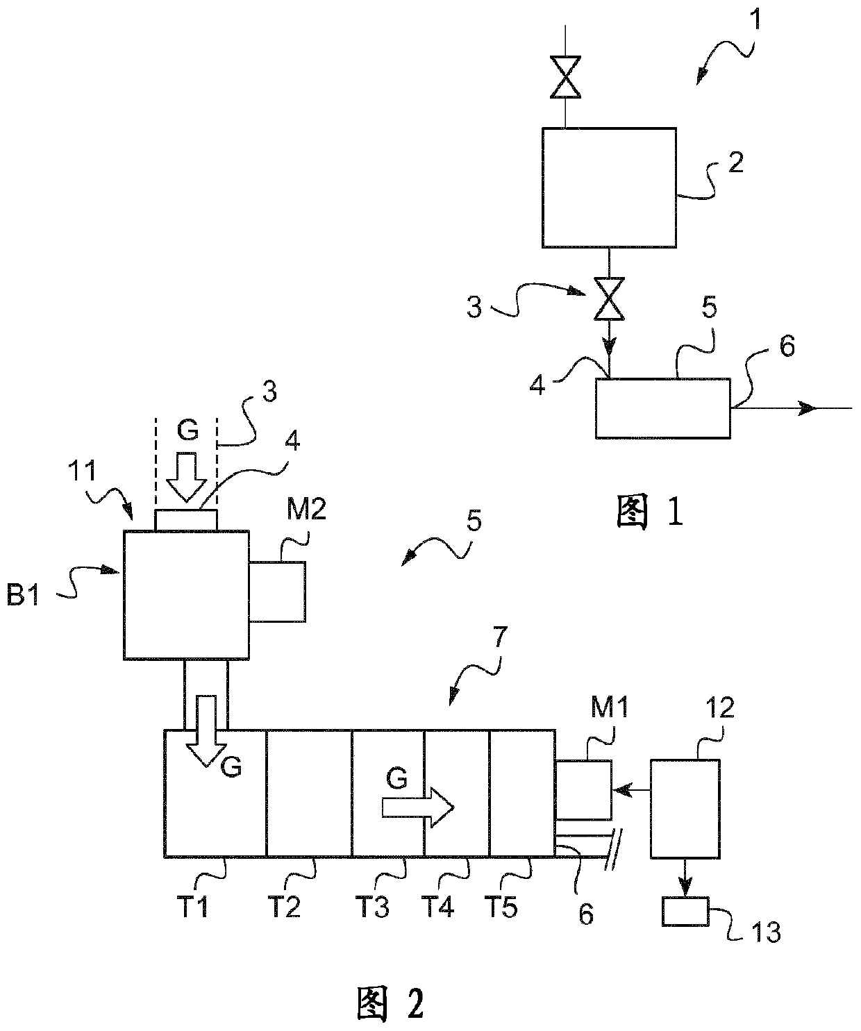
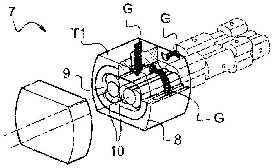
[0042] Roughing pumps are defined as positive displacement roughing pumps which, by means of two rotors, suck in, transfer and then discharge the gas to be pumped at atmospheric pressure. The rotor is carried by two shafts which are driven in rotation by the motor of the roughing vacuum pump.

[0043] A Roots blower is defined as a positive displacement vacuum pump which takes in, transfers and then discharges the gas to be pumped by means of a Roots-type rotor. The vacuum pump is installed on the upstream side of the rough vacuum pump and is in series with it. The rotor is carried by two shafts which are driven in r...


PUM


Abstract

The invention relates to a method for monitoring an operating state of a pumping device (5) connected to a process chamber (2) with a view to determining a faulty operating state of the pumping device(5), the pumping device (5) comprising at least one primary vacuum pump (7) comprising: a motor (M1) for driving the primary vacuum pump (7), and a variable speed drive (12) configured to control therotation speed of the motor (M1) and configured on the one hand to receive a first input parameter corresponding to a setpoint frequency (C) and a second input parameter corresponding to a motor current (i) and, on the other hand, to supply to the motor (M1) an output parameter corresponding to a control frequency (F), characterised in that a faulty operating state is determined when, in stationary operation (H), the difference between the first input parameter and the output parameter is no lower than 10% of the first input parameter, for a predetermined time period (T) of more than 3 seconds. The invention also relates to a pumping device and a facility.

Description

technical field [0001] The invention relates to a method for monitoring the operating state of a pumping device connected to a process chamber in order to determine a malfunctioning state of the pumping device. The invention also relates to a pumping device and a device using said method. Background technique [0002] A vacuum pump consists of two rotors which are driven by a motor to turn inside the pump body (stator). During rotation, the gas sucked in from the process chamber is trapped in the free space between the rotor and the stator, and then discharged to the outlet. [0003] Vacuum pumps are especially used in the process of making semiconductors, flat screens or photovoltaic substrates where subatmospheric pressures are required. However, the gases used in these processes may be converted to solid by-products which may deposit as a layer on the moving and static parts of the pump and cause clogging, which can then result from excessive friction between the rotor ...

Claims


Application Information

Patent Timeline
IPC IPC(8): F04C23/00F04C25/02F04C28/08F04C18/12F04C28/28G05B23/02
CPCF04C23/001F04C25/02F04C28/08F04C28/28F04C18/126G05B23/0283F04C2220/12F04C2240/403F04C2270/0525F04C2270/075F04C2270/095F04C2280/02F04C2270/051
Inventor S·布兰多林
Owner PFEIFFER VACUUM GMBH
Features
  • R&D
  • Intellectual Property
  • Life Sciences
  • Materials
  • Tech Scout
  • Unparalleled Data Quality
  • Higher Quality Content
  • 60% Fewer Hallucinations
Learn More