Heat pump utilization equipment

An equipment and heat pump technology, applied in the field of heat pump utilization equipment, can solve problems such as refrigerant leakage, and achieve the effect of suppressing leakage

Active Publication Date: 2021-10-15
MITSUBISHI ELECTRIC CORP
View PDF8 Cites 0 Cited by
  • Summary
  • Abstract
  • Description
  • Claims
  • Application Information

AI Technical Summary

Problems solved by technology

[0005] However, in this case, if the refrigerant leaks into the water circuit, the refrigerant mixed in the water in the water circuit may be discharged not only from the pressure relief valve provided on the outdoor unit but also from the pressure relief valve provided on the indoor unit. Happening
Therefore, there is a problem that the refrigerant may leak into the room through the water circuit

Method used


Image

  • Heat pump utilization equipment
  • Heat pump utilization equipment
  • Heat pump utilization equipment

Examples


Embodiment approach 1

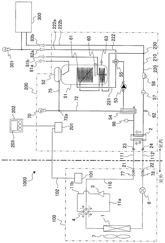
[0017] The heat pump utilization facility according to Embodiment 1 of the present invention will be described. figure 1 It is a circuit diagram showing a schematic configuration of the heat pump utilization facility according to the present embodiment. In this embodiment, a heat pump hot water supply and heating device 1000 is exemplified as a heat pump utilization device. Additionally, when including figure 1 In the drawings included below, the dimensional relationship, shape, etc. of each component may be different from actual ones.

[0018] Such as figure 1 As shown, the heat pump hot water heating apparatus 1000 has a refrigerant circuit 110 that circulates a refrigerant, and a water circuit 210 that circulates water. In addition, the heat pump hot water supply and heating apparatus 1000 includes an outdoor unit 100 installed outdoors (for example, outdoors) and an indoor unit 200 installed indoors. The indoor unit 200 is installed, for example, in a storage space suc...

Embodiment approach 2

[0089] A heat pump utilization facility according to Embodiment 2 of the present invention will be described. Figure 6 It is a circuit diagram showing a schematic configuration of the heat pump utilization facility according to the present embodiment. In addition, components having the same functions and actions as those in Embodiment 1 are assigned the same reference numerals and their descriptions are omitted. In the refrigerant circuit 110 of the present embodiment, a container 8 (for example, a storage tank) for storing refrigerant is provided between the heat source side heat exchanger 1 and the expansion device 6 .

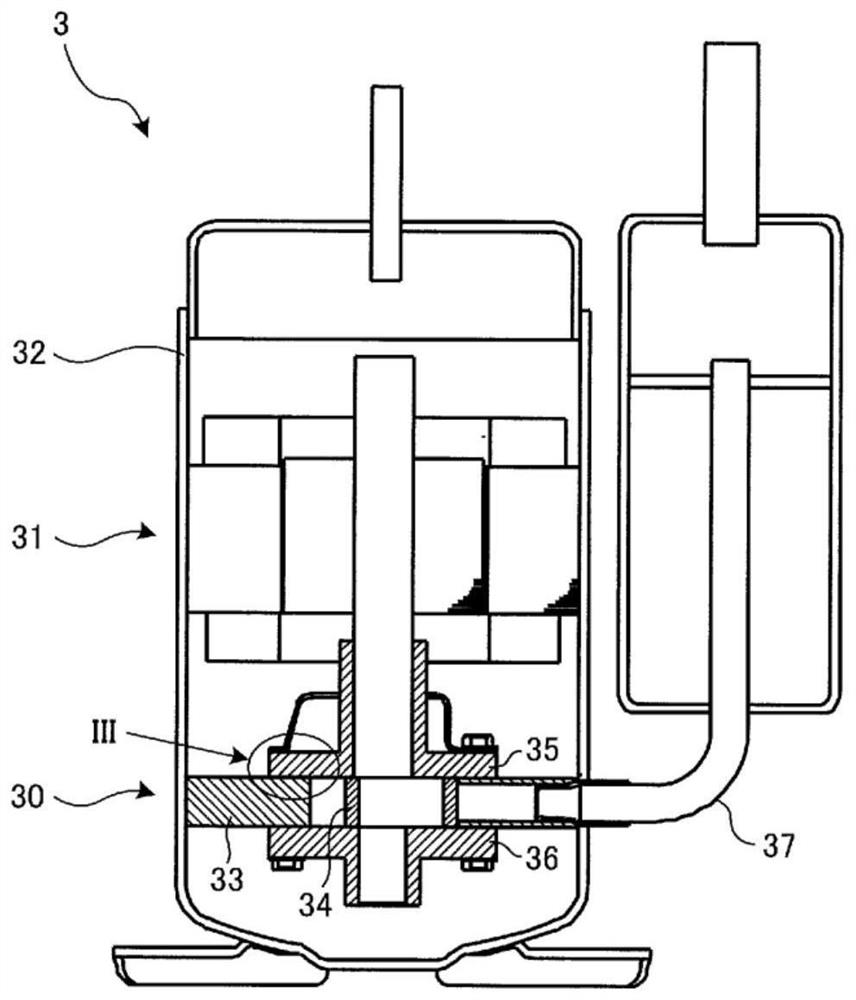
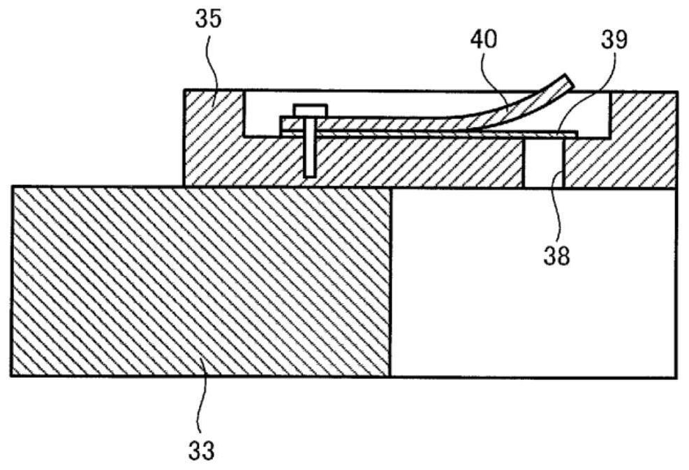
[0090] Figure 7 It is a cross-sectional view showing a schematic configuration of the compressor 3 of the heat pump utilization facility according to this embodiment. The compressor 3 of the present embodiment is a hermetically sealed high-pressure shell type scroll compressor. Such as Figure 7 As shown, the compressor 3 has a compression mechanism un...


PUM


Abstract

The heat pump utilization equipment includes a refrigerant circuit and a heat medium circuit, and the refrigerant circuit can perform a first operation in which the load-side heat exchanger functions as a condenser and a second operation in which the load-side heat exchanger functions as an evaporator, The main circuit of the heat medium circuit has a branch part and a confluence part. A pressure protection device and a refrigerant leakage detection device are connected to the main circuit. The pressure protection device is connected to the connection part. Between the side heat exchangers, or at the load side heat exchanger, the refrigerant leakage detection device is connected to the other side of the branch part or the confluence part, or is connected between the other side and the connection part, or is connected to the connection part, When refrigerant leakage into the heat medium circuit is detected, the refrigerant flow switching device is in the second operation state, the expansion device is in the closed state, and the compressor is operated.

Description

technical field [0001] The present invention relates to a heat pump utilization device having a refrigerant circuit and a heat medium circuit. Background technique [0002] Patent Document 1 describes an outdoor unit of a heat pump cycle device using a flammable refrigerant. This outdoor unit has a refrigerant circuit in which a compressor, an air heat exchanger, an expansion device, and a water heat exchanger are connected by piping, and a water circuit for supplying water heated by the water heat exchanger. Pressure relief valve for excessive rise in water pressure. Thus, even when the partition wall separating the refrigerant circuit and the water circuit in the water heat exchanger is damaged and the flammable refrigerant is mixed into the water circuit, the flammable refrigerant can be released to the outside through the pressure release valve. discharge. [0003] Patent Document 1: Japanese Patent Laid-Open No. 2013-167398 [0004] In heat pump utilization equipmen...

Claims


Application Information

Patent Timeline
Patent Type & Authority Patents(China)
IPC IPC(8): F25B1/00F25B49/02
CPCF24D19/1054F25B13/00F25B49/005F25B47/025F25B2313/003F25B2500/222F25B2600/2519F25B2400/19F25B2339/047F25B30/02F25B2400/12F24D11/02F25B41/22F25B49/022F25B2500/07F25B2500/221F24F11/36
Inventor 铃木康巨南迫博和铃木一隆美藤尚文服部太郎
Owner MITSUBISHI ELECTRIC CORP
Why Eureka
Try Eureka