Power transmission device

A technology of power transmission device and driving force, which is applied to transmission devices, electrical components, belts/chains/gears, etc., can solve the problems of reduced electromagnetic wave shielding performance and leakage, and achieve the effect of suppressing leakage

Active Publication Date: 2014-03-26
TOSHIBA MITSUBISHI-ELECTRIC IND SYST CORP
View PDF10 Cites 0 Cited by
  • Summary
  • Abstract
  • Description
  • Claims
  • Application Information

AI Technical Summary

Problems solved by technology

[0003] When the power transmission device is installed in the electromagnetic wave shielding room as described above, if the leakage of the radio wave through the through hole or the leakage of the radio wave transmitted through the shaft occurs, the shielding performance of the electromagnetic wave will be reduced.

Method used


Image

  • Power transmission device
  • Power transmission device
  • Power transmission device

Examples


Embodiment approach 1

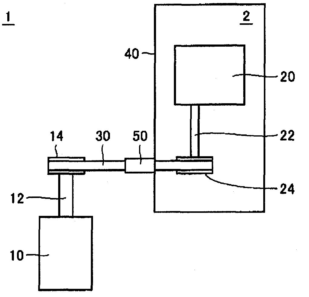
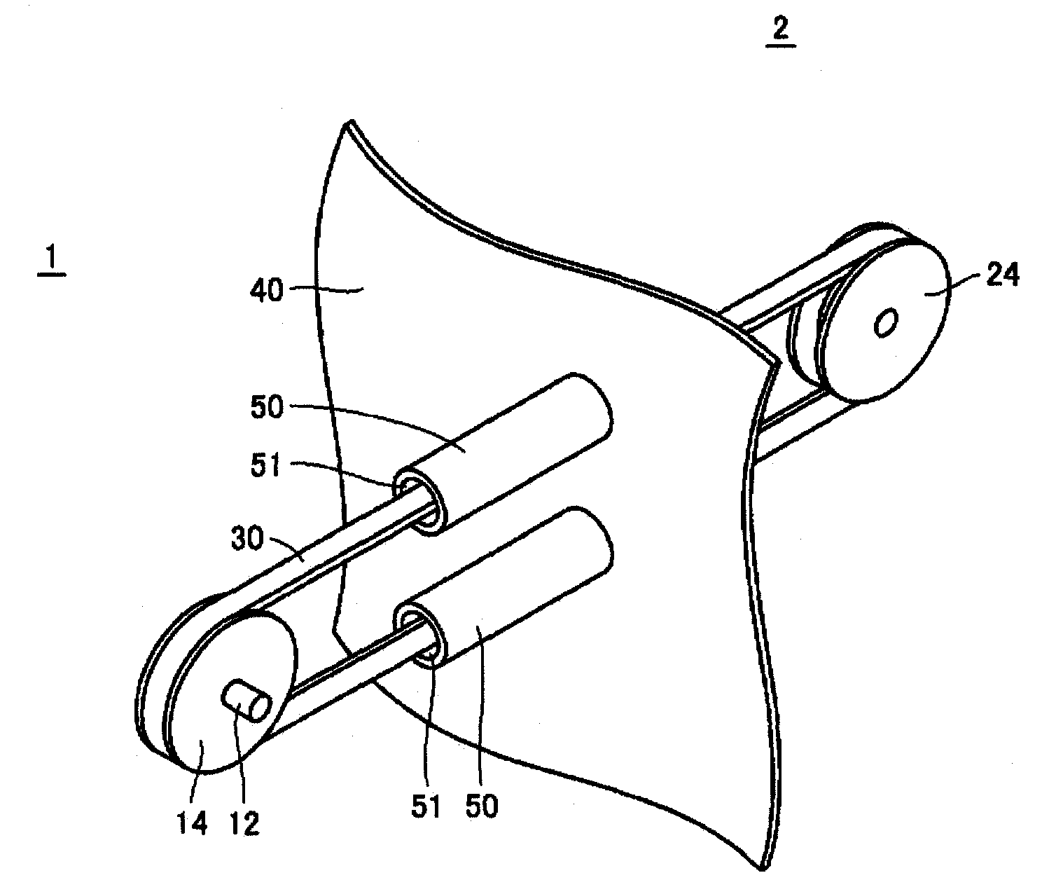
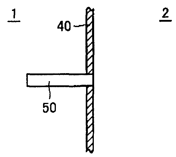
[0046] figure 1 It is a schematic plan view showing the structure of the power transmission device according to Embodiment 1 of the present invention. Such as figure 1 As shown, the power transmission device is a device for transmitting rotational driving force between the first space 1 and the second space 2 surrounded by the electromagnetic wave shielding wall 40 . The second space 2 is an area surrounded by the electromagnetic wave shielding walls 40 . The electromagnetic wave shielding wall 40 is formed by combining plate members of electric conductors, and can prevent propagation of electromagnetic waves between the first space 1 and the second space 2 . The electromagnetic wave shielding wall 40 constitutes the outer wall of the second space 2 serving as an electromagnetic wave shielding room. The second space 2 is a space adjacent to the first space 1 which is a space outside the electromagnetic wave shielding wall 40 , and is separated from the first space 1 by the ...

Embodiment approach 2

[0060] Figure 6 It is a perspective view showing a partial configuration of the power transmission device according to the second embodiment. exist Figure 6 2 shows a structure in which the belt 36 wound around the first pulley 16 and the second pulley 26 passes through the inside of the cylindrical member 56 and penetrates the electromagnetic wave shielding wall 40 according to the second embodiment.

[0061] The belt 36 according to Embodiment 2 is a toothed belt (cogged pulley) in which teeth are provided on one surface side and the other surface side is formed flat over the entire length of the belt shape. The first pulley 16 and the second pulley 26 on which the belt 36 is wound are toothed in a shape corresponding to the tooth shape of the toothed belt (Japanese: 歯付けベルト) in the circumferential direction of the outer peripheral surface. Pulley (gear pulley). Typically, the belt 36 can be used as a timing belt, and the first pulley 16 and the second pulley 26 can be u...

Embodiment approach 3

[0069] Figure 8 It is a perspective view showing a partial configuration of the power transmission device according to the third embodiment. exist Figure 8 In the diagram, the second pulley 28 of Embodiment 3, the belts 38 (38a, 38b) wound around the second pulley 28, and the cylindrical members 58a, 58b penetrated by the belt 38 are shown, and the first belt is omitted. Diagram of the wheel and electromagnetic wave shielding wall.

[0070] A plurality of (six in this case) pulley grooves 29 are formed in the second pulley 28 in the circumferential direction. exist Figure 8 The same number of pulley grooves 29 as the number of second pulleys 28 are also formed on the first pulley (not shown). A plurality of (four in this case) belts 38 are wound around the first pulley and the second pulley 28 to transmit a rotational driving force from the first pulley to the second pulley 28 . The belt 38 is a V-belt, and the first pulley and the second pulley 28 are V-pulleys. In t...


PUM


Abstract

A power transmission device includes an electromagnetic wave-shielding wall (40) partitioning a first space (1) and a second space (2) adjacent to the first space (1) and blocking propagation of an electromagnetic wave between the first space (1) and the second space (2). The power transmission device also includes a first pulley (14) arranged within the first space (1) and a second pulley (24) arranged within the second space (2). The power transmission device also includes a belt (30) placed on the first pulley (14) and the second pulley (24) and extending through the electromagnetic wave-shielding wall (40) to transmit rotational driving force between the first space (1) and the second space (2). From the electromagnetic wave-shielding wall (40) a hollow tubular member (50) is protruded and allows the first space (1) and the second space (2) to communicate with each other. The belt (30) extends through the inside of the tubular member (50).

Description

technical field [0001] The present invention relates to a power transmission device, in particular, to a power transmission device that transmits a rotational driving force through a shielding wall that prevents propagation of electromagnetic waves. Background technique [0002] Currently, an electromagnetic wave shielding room is generally formed for the purpose of shielding unnecessary electromagnetic waves intended to enter from the outside and preventing electromagnetic waves generated inside from leaking to the outside. The electromagnetic wave shielding room is formed by surrounding a target area with a plate member of an electrical conductor and grounding the plate member. When power is transmitted from one of the inside and the outside of the electromagnetic wave shielding room to the other, by forming a through hole on the plate member that prevents the propagation of electromagnetic waves, and installing a power transmission device that penetrates the through hole,...

Claims


Application Information

Patent Timeline
Patent Type & Authority Patents(China)
IPC IPC(8): F16H7/02E04B1/92E04H5/02H05K9/00
CPCF16H7/02H05K9/0018E04H5/02E04H9/14H05K9/00
Inventor 西宫和彦三浦秀树
Owner TOSHIBA MITSUBISHI-ELECTRIC IND SYST CORP
Why Eureka
Try Eureka