Radial oil collecting ring and under-ring oil supply lubricating device and method

An oil scavenger, oil supply technology, applied in bearing components, shafts and bearings, bearing cooling, etc., can solve the problems of low bearing lubrication efficiency and poor cooling effect, and achieve the effect of improving lubrication and cooling effect.

Active Publication Date: 2020-01-21
西安瑞谱捷特动力技术有限公司
View PDF8 Cites 9 Cited by
  • Summary
  • Abstract
  • Description
  • Claims
  • Application Information

AI Technical Summary

Problems solved by technology

[0003] Aiming at the defects and deficiencies in the prior art, the present invention provides a radial oil collector ring and an oil supply lubrication device and method under the ring, which solve the problems of low lubrication efficiency and poor cooling effect of existing bearings

Method used


Image

  • Radial oil collecting ring and under-ring oil supply lubricating device and method
  • Radial oil collecting ring and under-ring oil supply lubricating device and method
  • Radial oil collecting ring and under-ring oil supply lubricating device and method

Examples


Embodiment 1

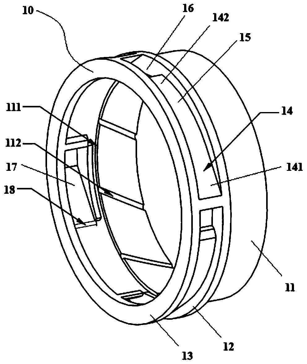
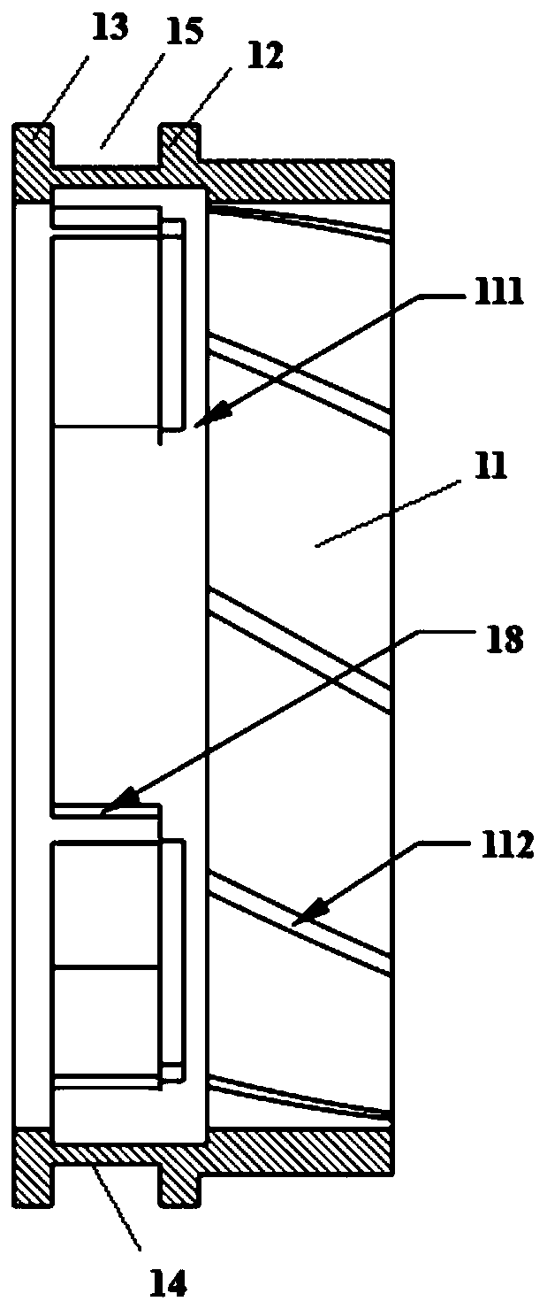
[0042] Such as figure 1 , figure 2 and image 3As shown, this embodiment provides a radial oil collector, including integrally formed: a cylindrical wall 11, a first annular retaining wall located at the end of the cylindrical wall 11 and coaxial with the cylindrical wall 11 12. The second annular retaining wall 13 parallel to the first annular retaining wall 12 and a plurality of oil collector vanes 14 connected between the first annular retaining wall 12 and the second annular retaining wall 13; the first annular retaining wall 12 and the plane where the second annular retaining wall 13 is located are all perpendicular to the central axis of the cylindrical wall 11, and the first annular retaining wall 12, the second annular retaining wall 13 and the oil collecting vanes 14 jointly form an oil collecting groove 15; One end of the oil collecting blade 14 corresponding to the oil groove 15 is the blade tip 141, and the other end is the blade root 142; The oil collection in...

Embodiment 2

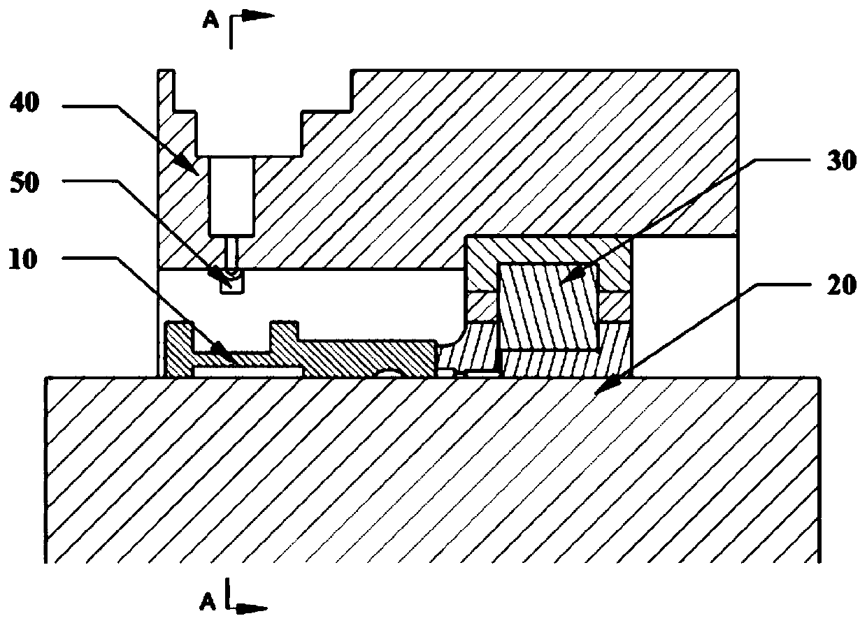
[0049] Such as Figure 3 to Figure 6 As shown, this embodiment provides an oil supply lubrication device under the ring, including the radial oil collector ring 10 in Embodiment 1, and also includes: a main shaft 20, a bearing 30 sleeved outside the main shaft 20, and a bearing 30 sleeved outside the bearing 30. The bearing seat 40 and the oil supply nozzle 50 arranged on the bearing seat 40 and connected to the oil supply passage; the oil supply nozzle 50 penetrates into the bearing seat 40 and aligns with the oil collection groove 15; the radial oil collection ring 10 is set on the main shaft 20 And it can rotate synchronously with the main shaft 20 , and one end provided with the oil delivery chute 112 is in close contact with the bearing 30 .

[0050] The bearing 30 includes a bearing inner ring 31 in contact with the main shaft 20 , a bearing outer ring 32 , and rolling elements 34 held by a cage 33 and provided between the bearing inner ring 31 and the bearing outer ring...

Embodiment 3

[0054] This embodiment provides a lubricating method for oil supply under the ring, which is realized by using the device in Embodiment 2, and specifically includes the following steps:

[0055] The lubricating oil jet sprayed from the oil supply nozzle is sprayed to the oil collecting groove of the radial oil collecting ring through the air field in the bearing cavity. The lubricating oil in the oil collection channel of the oil collection ring flows along the inner surface of the oil collection vane, flows through the blade protrusion on the oil collection vane, and then enters the front oil collection ring groove;

[0056] The blade protrusions on the oil collection vane can prevent the lubricating oil entering the front oil collection ring groove from being thrown out of the oil collection channel, and the lubricating oil in the front oil collection ring groove is transported to the rear oil collection ring groove along the oil delivery chute Inside, due to the oblique lay...


PUM


Abstract

The invention provides a radial oil collecting ring and an under-ring oil supply lubricating device and method. The radial oil collecting ring comprises a cylindrical wall, a first annular retaining wall arranged at the end part of the cylindrical wall and coaxial with the cylindrical wall, a second annular retaining wall parallel and opposite to the first annular retaining wall, and a plurality of oil collecting blades connected between the first annular retaining wall and the second annular retaining wall. The under-ring oil supply lubricating device comprises the radial oil collecting ring,a main shaft, a bearing sleeving the main shaft, a bearing base sleeving the bearing, and an oil supply nozzle arranged on the bearing base and connected with an oil supply way, wherein the oil supply nozzle penetrates into the bearing base, and is aligned to an oil collecting tank; the radial oil collecting ring sleeves the main shaft, and can synchronously rotate with the main shaft; and one end, provided with an oil conveying chute, of the radial oil collecting ring is tightly bonded with the bearing. The radial oil collecting ring can greatly improve the oil collecting efficiency; and theoil collecting quantity can satisfy the bearing lubricating and cooling requirements under the conditions of high speed, high temperature and heavy load to guarantee long-time stable work of the bearing.

Description

technical field [0001] The invention belongs to the field of bearing oil supply lubrication, and relates to a radial oil collection ring and an oil supply lubrication device and method under the ring. Background technique [0002] Rolling bearings are key components in high-speed rotating machinery. As the DN value increases, the spin speed of the rolling elements increases continuously, which may cause the bearing to fail and be damaged due to the increase in friction heat generation. At the same time, the bearing is required to be able to withstand heavy loads. In order to ensure that the high-speed rolling bearing can work reliably for a long time, the high-speed rolling bearing must be properly lubricated and cooled. With the increase of the spindle speed, due to the effect of wind resistance and centrifugal force in traditional jet lubrication, it is difficult for lubricating oil to enter the inside of the bearing, and the lubrication efficiency of the bearing is low, w...

Claims


Application Information

Patent Timeline
Patent Type & Authority Applications(China)
IPC IPC(8): F16C33/66F16C37/00
CPCF16C33/664F16C33/6659F16C37/007
Inventor 胡剑平刘振侠吕亚国吴丁毅朱鹏飞张丽芬刘振刚姜乐
Owner 西安瑞谱捷特动力技术有限公司
Why Eureka
Try Eureka