Network topology collection method and device

A network topology and acquisition device technology, applied in the field of communication, to solve flooding problems, reduce signaling overhead, and save energy consumption

Inactive Publication Date: 2020-01-21
FUJITSU LTD
View PDF4 Cites 1 Cited by
  • Summary
  • Abstract
  • Description
  • Claims
  • Application Information

AI Technical Summary

Problems solved by technology

[0006] Embodiments of the present invention provide a network topology acquisition method and device, which can be applied to various types of Internet protocol networks, solve the flooding problem caused by broadcast transmission, be easy to implement, have relatively small signaling overhead, and save energy consumption

Method used


Image

  • Network topology collection method and device
  • Network topology collection method and device
  • Network topology collection method and device

Examples


Embodiment 1

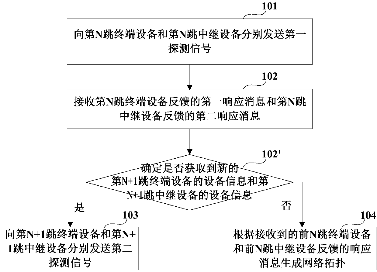
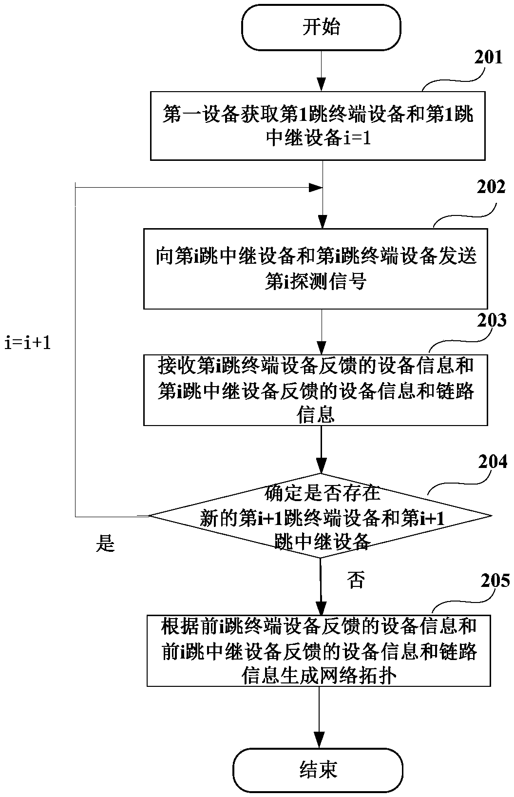
[0049] Embodiment 1 provides a network topology acquisition method, which is applied to a first device in the network. For example, the first device may be a management device (Manager) in a network supporting the HTIP protocol. figure 1 It is a flow chart of the network topology acquisition method in Embodiment 1, please refer to figure 1 , the method includes:

[0050] Step 101, sending a first detection signal to the Nth hop terminal device and the Nth hop relay device respectively; N is an integer greater than or equal to 1;

[0051] Step 102, receiving the first response message fed back by the Nth hop terminal device and the second response message fed back by the Nth hop relay device, the first response message including the device information of the Nth hop terminal device, and the second response message Including the device information of the Nth hop relay device and first link information, where the first link information includes device information of a device tha...

Embodiment 2

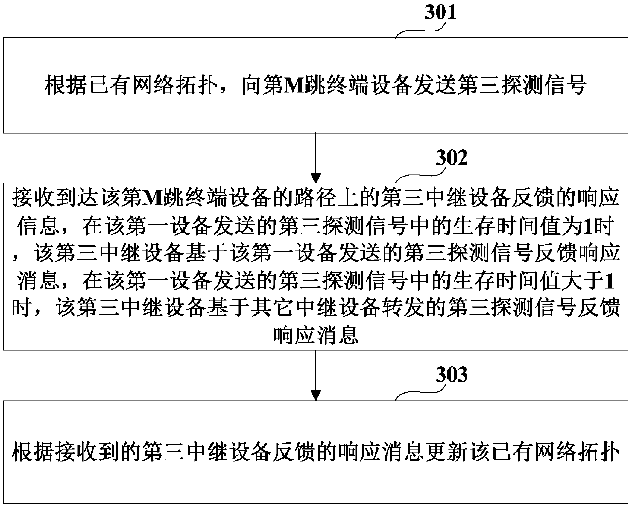
[0077] Since the network is dynamically changing in real time, that is, the devices in the network and the connection relationship between each device are not static, therefore, Embodiment 2 provides a network topology acquisition method, which is applied to the first device in the network, for example , the first device may be a management device (Manager) in a network supporting the HTIP protocol, and the existing network topology may be updated through the network topology acquisition method in Embodiment 2 to obtain an updated network topology, image 3 It is a flow chart of the network topology acquisition method in Embodiment 2, please refer to image 3 , the method includes:

[0078] Step 301, according to the existing network topology, send a third detection signal to the Mth hop terminal device, where M is an integer greater than 1;

[0079] Step 302: Receive response information fed back by a third relay device on the path to the Mth hop terminal device, where the r...

Embodiment 3

[0103] Embodiment 3 provides a network topology acquisition method, which is applied to a relay device in the network. For example, the relay device may be a network device (NW) in a network supporting the HTIP protocol, and the hop count of the relay device is the P-th hop, and P is an integer greater than or equal to 1; the method on the relay device side corresponds to the method in Embodiment 1 and 2, and part of the content in Embodiment 1 and 2 is merged here, and the repeated content is no longer repeat, Figure 5 It is a flow chart of the network topology acquisition method in Embodiment 3, please refer to Figure 5 , the method includes:

[0104] Step 501, receiving a fourth detection signal sent by the first device; the fourth detection signal includes a destination address and a time-to-live value;

[0105] Step 502, when the destination address in the fourth detection signal is the P-th hop relay device, feed back a fifth response message to the first device, whe...


PUM


Abstract

The embodiment of the invention provides a network topology collection method and a network topology collection device. The method comprises the following steps: respectively sending a first detectionsignal to an Nth hop terminal device and an N hop relay device; receiving a first response message fed back by the Nth hop terminal device and a second response message fed back by the Nth hop relay device, when the equipment information of the (N + 1) hop of terminal equipment and the equipment information of the (N + 1) hop of relay equipment which are different from the obtainedprevious N hop of terminal equipment and previous N hop of relay equipment are obtained according to the first link information, respectively sending a second detection signal to the (N + 1) hopof terminal equipment and the (N + 1) hop of relay equipment; and when the device information of the terminal device and the device information of the relay device different from the obtained first N-hop terminal device and the obtained first N-hop relay device are not obtained according to the first link information, generating a network topology according to received response messages fed back by the first N-hop terminal device and the first N-hop relay device.

Description

technical field [0001] The present invention relates to the technical field of communication, in particular to a network topology acquisition method and device thereof. Background technique [0002] Currently, the Home network topology identifying protocol (Home network Topology Identifying Protocol, HTIP) can be used to identify the topology of the home network and check the connection status of the terminal device and / or relay device, which can enable the management device in the network to collect Device information and link information are used to identify network topology, thereby helping home network users locate and solve network problems. [0003] In the existing HTIP protocol, the data link (L2) layer on the terminal device, the network layer (L3) agent sends device information, and the data link (L2) layer on the relay device sends device information and link information , where the L3 agent uses the Universal Plug and Play Protocol (UPnP), the L2 agent uses the L...

Claims


Application Information

Patent Timeline
Patent Type & Authority Applications(China)
IPC IPC(8): H04L12/24H04L12/751H04L45/02
CPCH04L41/12H04L45/02
Inventor 王昊薛文倩易粟范小菁王乐菲松仓隆一
Owner FUJITSU LTD
Why Eureka
Try Eureka