Machine tool bottom waste material collecting, compressing and processing device

A compression processing device and waste material collection technology, which is applied to metal processing machinery parts, maintenance and safety accessories, metal processing equipment, etc., can solve the problems of troublesome cleaning process, inability to adjust, and less waste, and achieve easy adjustment and cost saving. Effect

Active Publication Date: 2020-01-24
温岭市佳德机械有限公司
View PDF5 Cites 3 Cited by
  • Summary
  • Abstract
  • Description
  • Claims
  • Application Information

AI Technical Summary

Problems solved by technology

[0002] The machine tool will generate a lot of waste during use. Generally, there will be a waste collection tank on the lower side of the machine tool’s processing position, but there will be a lot of space between the waste, which will result in less waste that can be stored. The collection tank is cleaned, and the cleaning process is extremely troublesome
In the prior art, there have been machine tools that directly output the generated waste, which is convenient for manual cleaning. However, the cleaning function is integrated with the machine tool, and the machine tool needs to be replaced as a whole. Reduce costs, but the sizes of waste collection tanks that come with different machine tools are not consistent. The existing ones that can be installed cannot be adjusted according to the size, and can only be produced according to the corresponding specifications, and are only suitable for waste collection tanks of this specification. limited use

Method used


Image

  • Machine tool bottom waste material collecting, compressing and processing device
  • Machine tool bottom waste material collecting, compressing and processing device
  • Machine tool bottom waste material collecting, compressing and processing device

Examples


Embodiment Construction

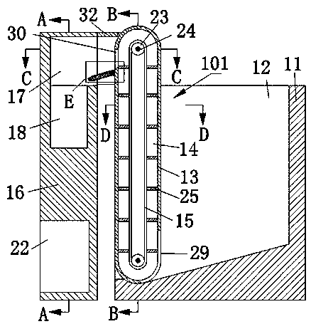
[0021] Combine below Figure 1-Figure 6 The present invention is described in detail, and for convenience of description, the orientations mentioned below are now stipulated as follows: figure 1 The up, down, left, right, front and back directions of the projection relationship itself are the same.

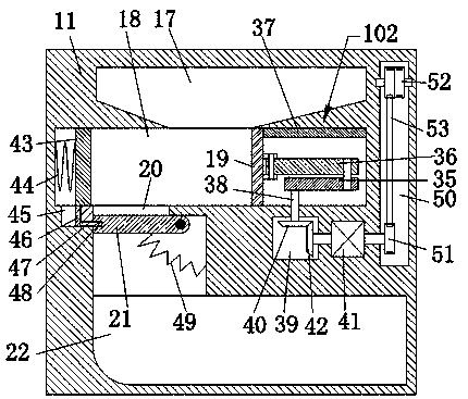
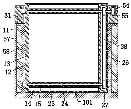
[0022] The invention relates to a device for collecting and compressing waste materials at the bottom of a machine tool, which is mainly used for compressing and collecting waste materials produced by machine tool processing. The invention will be further described below in conjunction with the drawings of the invention:

[0023] A waste collection and compression treatment device at the bottom of a machine tool according to the present invention includes a collection box 11, the left side of the collection box 11 is provided with a collection chamber 12 with an opening upward and to the left, and the left side of the collection chamber 12 can be turned over is provided with an o...


PUM


Abstract

The invention discloses a machine tool bottom waste material collecting, compressing and processing device. The machine tool bottom waste material collecting, compressing and processing device comprises a collecting box; a collecting cavity with an upward and leftward opening is arranged on the left side in the collecting box; a turnover baffle is arranged on the left side in the collecting cavityin a turnover manner; conveying cavities are arranged in the turnover baffle; conveying devices are arranged in the conveying cavities; a conveying belt is arranged in the conveying devices; waste materials accumulated in the collecting cavities enters the lower sides in the conveying cavities; the waste materials are transported upwards by the conveying belt; a compressing box is arranged on theleft side of the collecting box; a material collecting cavity with a rightward opening is arranged on the upper side of the compressing box; and a compressing device is arranged on the lower side ofthe material collecting cavity. According to the machine tool bottom waste material collecting, compressing and processing device, the device is installed in a waste material collecting groove of a machine tool, so that the function of waste material collecting and compressing of a common machine tool is increased, disassembly or refitting is not needed, a new machine tool is not needed, the installation is convenient, the cost is saved, and meanwhile, the manual adjustment can be carried out according to the size of the waste material collecting groove, and adjustment is simple and convenient.

Description

technical field [0001] The invention relates to the technical field of machine tool accessories, in particular to a device for collecting and compressing waste materials at the bottom of a machine tool. Background technique [0002] The machine tool will generate a lot of waste during use. Generally, there will be a waste collection tank on the lower side of the machine tool’s processing position, but there will be a lot of space between the waste, which will result in less waste that can be stored. The collection tank is cleaned, and the cleaning process is extremely troublesome. In the prior art, there have been machine tools that directly output the generated waste, which is convenient for manual cleaning. However, the cleaning function is integrated with the machine tool, and the machine tool needs to be replaced as a whole. Reduce costs, but the sizes of waste collection tanks that come with different machine tools are not consistent. The existing ones that can be inst...

Claims


Application Information

Patent Timeline
Patent Type & Authority Applications(China)
IPC IPC(8): B23Q11/00
CPCB23Q11/0067
Inventor 李黄桥
Owner 温岭市佳德机械有限公司
Why Eureka
Try Eureka