Injection mold with good ejection effect

An injection mold and ejection technology, which is applied in the field of molds, can solve problems such as sticking and injection molded parts cannot be ejected smoothly, and achieve the effect of simple principle, good ejection effect, and reduced sticking

Inactive Publication Date: 2020-01-24
苏州丰硕模具有限公司
View PDF4 Cites 5 Cited by
  • Summary
  • Abstract
  • Description
  • Claims
  • Application Information

AI Technical Summary

Problems solved by technology

[0002] With the continuous development of the economy and the continuous progress of society, it provides a wealth of material consumer goods, creating good conditions for improving people's living standards and pursuing personalized life, thus accelerating the demand for material consumer goods, and plastic products are many One of the material consumer goods, as we all know, the injection mold is a common mold used to form plastic products. Through the injection mold, a variety of plastic products can be formed to meet the various needs of people. After the products in the injection mold are formed , it is necessary to demould the product. The mold is widely used in the current industrial production, and usually includes a female mold and a male mold, and an ejection mechanism for ejecting the formed product. The ejection mechanism generally includes an ejector pin and a needle plate One end of the thimble passes through the movable mold to support the product located between the female mold and the male mold, and the other end is fixed on the needle plate. When demoulding, the ejector stick on the injection molding machine pushes the needle plate to drive the needle plate to move upward to lift the product. Now In the prior art, the thimble tends to stick to the injection molded part when ejecting the injection molded part, causing the injection molded part to be unable to be ejected smoothly

Method used


Image

  • Injection mold with good ejection effect
  • Injection mold with good ejection effect
  • Injection mold with good ejection effect

Examples


Embodiment Construction

[0018] The following will clearly and completely describe the technical solutions in the embodiments of the present invention with reference to the accompanying drawings in the embodiments of the present invention. Obviously, the described embodiments are only some, not all, embodiments of the present invention. Based on the embodiments of the present invention, all other embodiments obtained by persons of ordinary skill in the art without making creative efforts belong to the protection scope of the present invention.

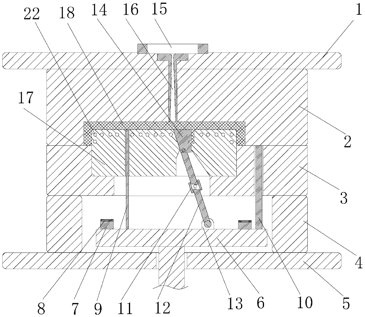
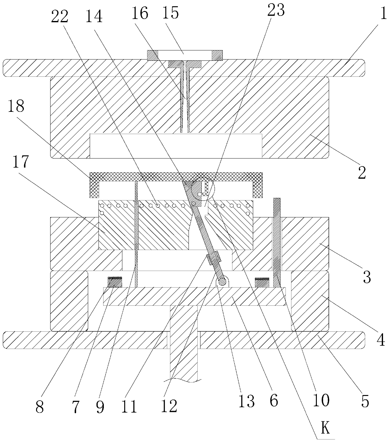
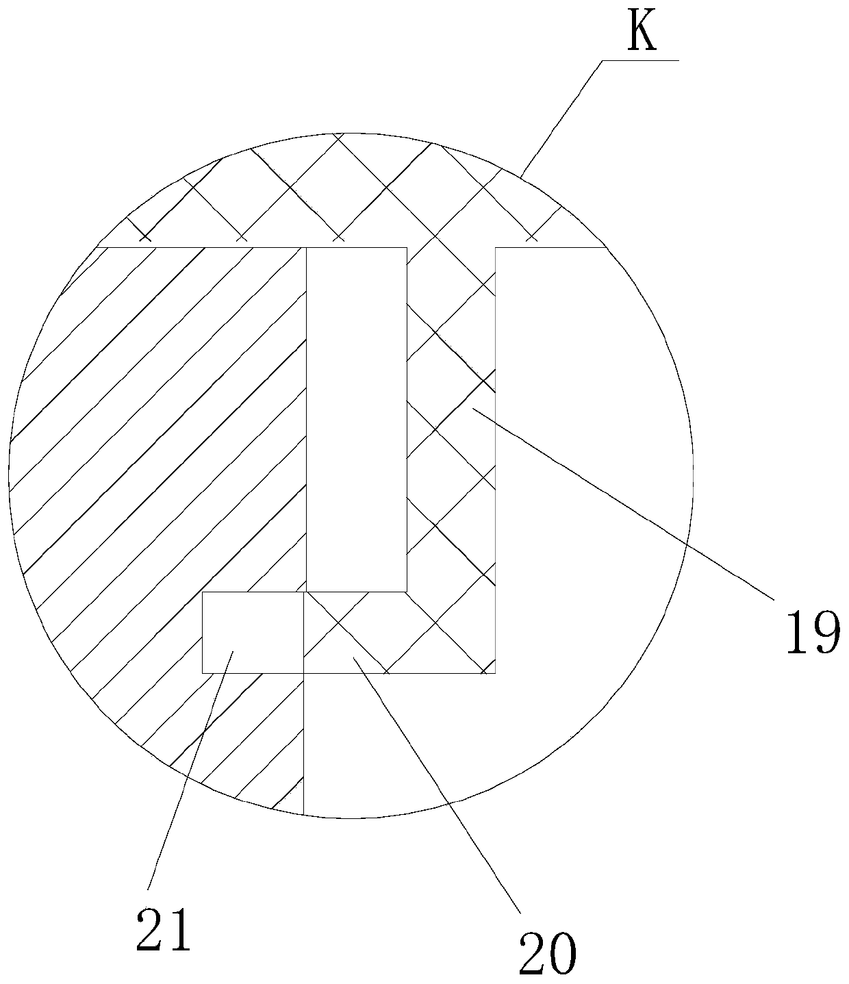
[0019] see Figure 1~3 , the present invention provides a technical solution:

[0020] An injection mold with good ejection effect, comprising an upper template 2 and a lower template 3, the upper template 2 is fixedly installed on the upper bottom plate 1, a lower bottom plate 5 is arranged below the upper bottom plate 1, and the lower bottom plate 5 A pair of mold feet 4 are fixedly connected on the upper side, the lower template 3 is fixedly installed on t...


PUM


Abstract

The invention discloses an injection mold with a good ejection effect. The injection mold comprises an upper template and a lower template, wherein the upper template is fixedly installed on an upperbaseplate; a lower baseplate is disposed under the upper baseplate; a pair of mold pins is fixedly connected to the lower baseplate; the lower template is fixedly installed on upper ends of the mold pins; an embedded block is fixedly installed on the lower template; a mold cavity is formed at a joint between the embedded block and the upper template; an injection molding part is injected in the mold cavity; an ejection pin plate is installed between the mold pins on left and right sides in a slide manner; an ejection rod is in rotatable connection to the ejection pin plate; a wedged ejection block is in rotatable connection to the upper end of the ejection rod; and the wedged ejection block is installed inside an embedded block groove which is formed in the embedded block in a slide manner. The invention provides the injection mold with the good ejection effect, wherein the structure is rational; working principles are simple; working stability is high; and mold release is smooth.

Description

technical field [0001] The invention relates to the technical field of molds, in particular to an injection mold with good ejection effect. Background technique [0002] With the continuous development of the economy and the continuous progress of society, it provides a wealth of material consumer goods, creating good conditions for improving people's living standards and pursuing personalized life, thereby accelerating the demand for material consumer goods, and plastic products are many One of the material consumer goods, as we all know, injection molds are commonly used molds for molding plastic products. Various forms of plastic products can be formed through injection molds to meet people's various needs. After the products in the injection mold are formed , it is necessary to demould the product. The mold is widely used in the current industrial production, and usually includes a female mold and a male mold, and an ejection mechanism for ejecting the formed product. Th...

Claims


Application Information

Patent Timeline
Patent Type & Authority Applications(China)
IPC IPC(8): B29C45/33B29C45/40B29C45/72
CPCB29C45/332B29C45/40B29C45/7207B29C2045/334
Inventor 丰硕刘文雄
Owner 苏州丰硕模具有限公司
Why Eureka
Try Eureka