
Laminating roller, laminating jig, and laminating method of flexible screen and curved cover plate

A technology of laminating jigs and laminating rollers, applied in the direction of manufacturing tools, presses using rotating pressure components, presses, etc., can solve problems such as the difficulty of laminating flexible screens and curved cover plates, and achieve optimal lamination sequence. , Simplify deformation, and achieve the effect of fitting

Active Publication Date: 2021-10-29
BOE TECH GRP CO LTD +1
View PDF8 Cites 0 Cited by
  • Summary
  • Abstract
  • Description
  • Claims
  • Application Information

AI Technical Summary

Problems solved by technology

[0005] In view of the shortcomings of the existing methods, this application proposes a bonding roller, a bonding fixture, and a bonding method for the flexible screen and the curved cover to solve the difficulty in bonding the flexible screen and the curved cover in the prior art question

Method used


Image

  • Laminating roller, laminating jig, and laminating method of flexible screen and curved cover plate
  • Laminating roller, laminating jig, and laminating method of flexible screen and curved cover plate
  • Laminating roller, laminating jig, and laminating method of flexible screen and curved cover plate

Examples


Embodiment Construction

[0053] The present application is described in detail below, and examples of embodiments of the present application are shown in the drawings, wherein the same or similar reference numerals denote the same or similar components or components having the same or similar functions throughout. Also, detailed descriptions of known technologies will be omitted if they are not necessary to illustrate the features of the present application. The embodiments described below by referring to the figures are exemplary only for explaining the present application, and are not construed as limiting the present application.

[0054] Those skilled in the art can understand that, unless otherwise defined, all terms (including technical terms and scientific terms) used herein have the same meanings as commonly understood by those of ordinary skill in the art to which this application belongs. It should also be understood that terms, such as those defined in commonly used dictionaries, should be ...


PUM


Abstract

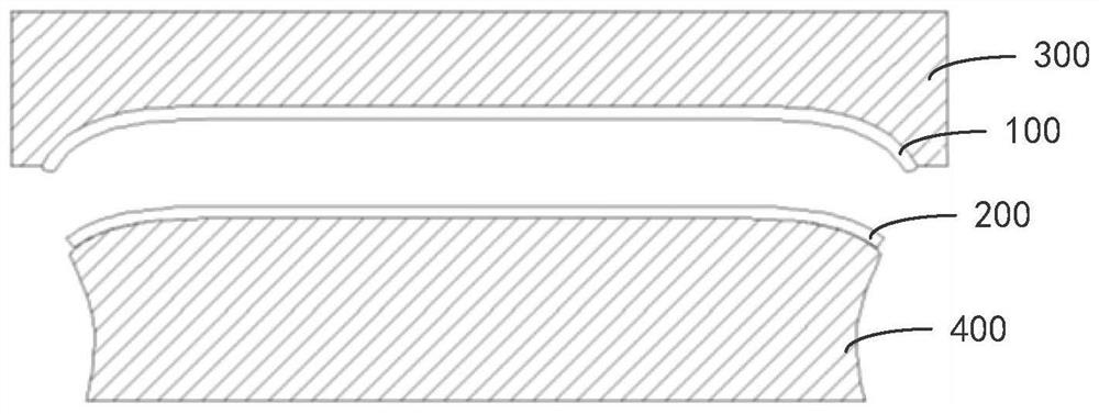
Embodiments of the present application provide a bonding roller, a bonding jig, and a bonding method of a flexible screen and a curved cover. The bonding roller includes: a roller and a bonding part; the bonding part is made of elastic material, and the bonding part has a first bottom surface, a second bottom surface and a peripheral surface; the second bottom surface is bonded to the surface of the roller; the first The bottom surface includes a main fitting surface and an end fitting surface; the main fitting surface is parallel to the second bottom surface and is used to match the bottom body of the curved cover; the end fitting surface is used to match the bottom corner of the curved cover The end bonding surface protrudes from the main bonding surface; the peripheral surface connects the first bottom surface and the second bottom surface; the peripheral surface is used to cooperate with the curved surface of the curved cover plate. The embodiment of the present application adopts rolling lamination, and optimizes the local lamination sequence of the flexible screen to improve the stress on the flexible screen so as to achieve full lamination of the flexible screen and the curved cover.

Description

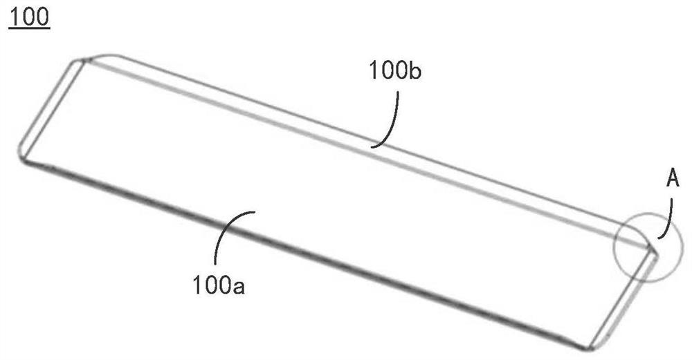
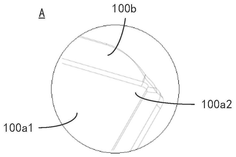
technical field [0001] The present application relates to the technical field of lamination of flexible screens. Specifically, the present application relates to a lamination roller, a lamination jig, and a lamination method of a flexible screen and a curved cover. Background technique [0002] With the rapid development of display technology, various types of display products gradually appear in people's lives. Curved display products are favored by more and more consumers because of their advantages such as better sensory experience of curved screens, more comfortable wearing experience due to strong bending and plasticity of flexible curved screens, or better three-dimensional display effects. [0003] A curved screen includes a fitted curved cover and a flexible screen. Such as figure 1 and figure 2 As shown, the curved cover panel includes a base body with a relatively small curvature, and bottom end portions or corners with a relatively large curvature. The part o...

Claims


Application Information

Patent Timeline
Patent Type & Authority Patents(China)
IPC IPC(8): B30B3/00B30B15/00
CPCB30B3/005B30B15/00
Inventor 石佳凡陈立强王作家王青松李刚
Owner BOE TECH GRP CO LTD
Learn More