
Tray positioning device for timing part detection

A technology of positioning device and parts, applied in the direction of conveyor objects, transportation and packaging, etc., can solve the problems of easy movement, lack of limit structure on the material tray, affecting detection, etc., to achieve easy clamping, avoid movement, and simple operation. Effect

Active Publication Date: 2020-01-24
苏州工业园区时运精工有限公司
View PDF3 Cites 0 Cited by
  • Summary
  • Abstract
  • Description
  • Claims
  • Application Information

AI Technical Summary

Problems solved by technology

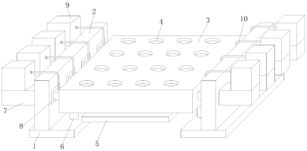
[0003] During the processing and production of timing parts, they are generally conveyed by conveyors, conveyed on the conveyor belt, moved to the detection area, and grasped through the mechanical wall, while timing parts are generally placed on the tray for storage. When detecting and grabbing, the material tray lacks a limit structure, which is prone to movement and affects the detection

Method used


Image

  • Tray positioning device for timing part detection
  • Tray positioning device for timing part detection
  • Tray positioning device for timing part detection

Examples


Embodiment Construction

[0027] In order to make the purpose, features and advantages of the present invention more obvious and understandable, the technical solutions in the embodiments of the present invention will be clearly and completely described below in conjunction with the accompanying drawings in the embodiments of the present invention. Obviously, the following The described embodiments are only some, not all, embodiments of the present invention. Based on the embodiments of the present invention, all other embodiments obtained by persons of ordinary skill in the art without making creative efforts belong to the protection scope of the present invention.

[0028] The technical solutions of the present invention will be further described below in conjunction with the accompanying drawings and through specific implementation methods.

[0029] In the description of the present invention, it should be understood that the orientations or positional relationships indicated by the terms "upper", "...


PUM


Abstract

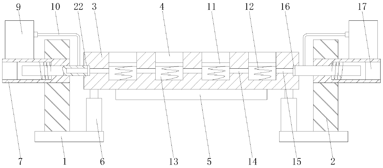
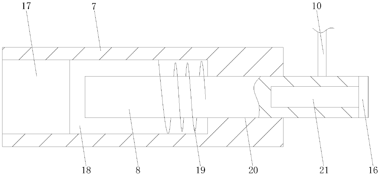
The invention discloses a tray positioning device for timing part detection. The device comprises a base plate, a vertical plate, a tray, a groove, a conveying belt, a cylinder, a fixed rectangular pipe, a movable iron rod, an air pump, a hose, a matching support piece, a circular piece, a rubber sealing ring, a center hole, a first spring, a circular cavity, a first connecting hole, a second connecting hole, a rubber rectangular ring, an electromagnet, a first rectangular hole, a second spring, a second rectangular hole, a circular hole and an embedding hole. The device is reasonable in structure; the tray is conveyed on the conveying belt, is retained in a detecting area for positioning and fixation after conveying, and is limited through a telescopic butting structure and the embeddinghole to prevent movement, and the limiting process needs no manual operation; and when the positioning is performed in an appointed position, the bottom butting of the tray is realized through the cylinder to achieve further limiting, so that the limiting and fixing effect is better, and the influence on the tray machining stability by shaking of the tray due to external acting force after fixation and limiting is prevented.

Description

technical field [0001] The invention relates to a positioning device, in particular to a material tray positioning device for timing component detection, and belongs to the technical field of timing component detection application. Background technique [0002] The detection of timing parts is generally an internal component in the timing device. After the timing parts are processed, they can be protected by installing an outer shell to achieve protection; the timing parts need to be tested during the processing process. [0003] During the processing and production of timing parts, they are generally conveyed by conveyors, conveyed on the conveyor belt, moved to the detection area, and grasped through the mechanical wall, while timing parts are generally placed on the tray for storage. When detecting and grabbing, the material tray lacks a limit structure, which is prone to movement and affects detection. Therefore, in view of the above problems, a positioning device for a...

Claims


Application Information

Patent Timeline
IPC IPC(8): B65G47/24
CPCB65G47/24
Inventor 许啸
Owner 苏州工业园区时运精工有限公司
Features
  • Generate Ideas
  • Intellectual Property
  • Life Sciences
  • Materials
  • Tech Scout
  • Unparalleled Data Quality
  • Higher Quality Content
  • 60% Fewer Hallucinations
Learn More