Automatic winding device

A technology of winding device and driving device, which is applied in the directions of packaging, winding strips, transportation and packaging, etc. It can solve the problems of low packaging efficiency of a single part, failure to realize automatic winding, and prolonged packaging time, so as to save labor costs , tidy arrangement, and the effect of reducing manufacturing costs

Pending Publication Date: 2020-01-24
TAICANG KELITE METAL COMPONENTS TECH CO LTD
View PDF0 Cites 3 Cited by
  • Summary
  • Abstract
  • Description
  • Claims
  • Application Information

AI Technical Summary

Problems solved by technology

The main disadvantages of the above-mentioned winding mechanism are: the two rollers are placed horizontally, and the axes of the three rollers are arranged in an equilateral or isosceles triangle. material, unable to realize automatic winding, can only manually add equipment semi-automatic or purely manual winding method, increase labor cost
[0003] The existing winding device can only use manual plus equipment, semi-automatic or purely manual winding, and the packaging efficiency of a single part is low
It is necessary to pre-cut the material that needs to be rolled into a certain size, and then use manual plus equipment semi-automatic or purely manual winding method. After the packaging is completed, the shape specifications (length and diameter) of the parts are different, the shapes are different, and the uniformity is poor. ; Manually adding equipment, semi-automatic or purely manual winding method, increases the labor intensity for the packaging of the final parts into the container (turnover box or carton), prolongs the packaging time, and is inefficient, and uses manual cutting, placing packaging film, etc.

Method used


Image

  • Automatic winding device
  • Automatic winding device
  • Automatic winding device

Examples


Embodiment Construction

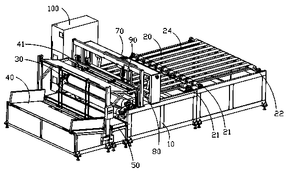
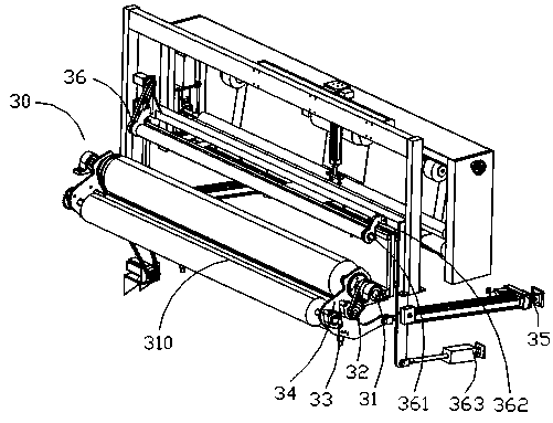
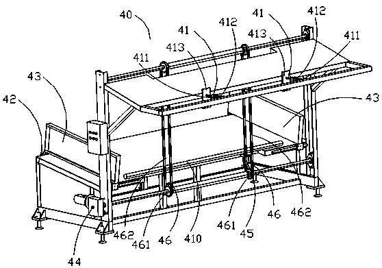
[0026] Such as figure 1 As shown, an embodiment of the present invention discloses an automatic winding device, comprising: a frame 10, a conveying mechanism 20 arranged on the frame 10, a multi-axis linkage winding mechanism 30, and an automatic upper tubular material conveying device 40, wherein, the automatic upper tubular material conveying equipment 40 includes a discharge push rod mechanism 41, and the discharge push rod mechanism 41 can move to release the tubular material 410 to the preset position of the multi-axis linkage winding mechanism 30, the The conveying mechanism 20 is used to convey the tubular material 410 to the multi-axis linkage winding mechanism 30 . Preferably, the frame 10 is cut and welded from a 40x80mm, 50x100mm, 60*120mm square tube or a 1-20mm plate.

[0027]Conveying mechanism 20 comprises conveying main transmission shaft 21, conveying driven shaft 22, conveying driving device 23 and being arranged on described conveying main driving shaft 21,...


PUM

PropertyMeasurementUnit
diameteraaaaaaaaaa
diameteraaaaaaaaaa

Abstract

The invention provides an automatic winding device. The automatic winding device comprises a rack, a conveying mechanism, a multi-shaft linkage winding mechanism and automatic tubular material feedingconveying equipment, wherein the conveying mechanism, the multi-shaft linkage winding mechanism and the automatic tubular material feeding conveying equipment are arranged on the rack; the automatictubular material feeding conveying equipment comprises a discharging push rod mechanism; the discharging push rod mechanism can move so as to release tubular materials to the preset position of the multi-shaft linkage winding mechanism; and the conveying mechanism is used for conveying the tubular materials to the multi-shaft linkage winding mechanism. According to the scheme, the wound materialsare automatically cut, automatically fed and automatically fed to paper tubes on the automatic winding device, through the structural design of the multi-shaft linkage winding mechanism, the wound materials can be well and automatically wound, packaging paper or packaging films are automatically discharged, and the packaging paper or the packaging films are automatically cut according to the product specification; manual pre-winding is not needed, the production efficiency is improved, and the manufacturing cost is reduced; and through the structural design, the performance is stable, and theprecision is high.

Description

technical field [0001] The invention relates to an automatic winding device, which belongs to the field of automatic winding devices. Background technique [0002] The winding mechanism of the existing winding device adopts a simple double-roller drive with the same diameter and generally arranged in parallel or a three-roller drive with a simple triangular arrangement of the axis. The double-roller drive rollers are placed horizontally or vertically. ; The three-roller transmission adopts two horizontal rollers, and the third roller is placed above the middle of the two horizontal rollers to form an isosceles or equilateral triangle. The main disadvantage of the above-mentioned winding mechanism is that the two rollers are placed horizontally, and the axes of the three rollers are placed in an equilateral or isosceles triangle. Material, can not realize automatic winding, can only manually add equipment semi-automatic or purely manual winding method, increase labor cost. ...

Claims


Application Information

Patent Timeline
Patent Type & Authority Applications(China)
IPC IPC(8): B65H19/30B65H18/10B65H35/02B65H35/06B65B25/14B65B61/06B65B11/10B65C9/14B65C7/00B65B61/28
CPCB65B11/10B65B25/146B65B61/06B65B61/28B65C7/00B65C9/14B65H18/10B65H19/305B65H35/02B65H35/06B65H2403/55
Inventor 张同响
Owner TAICANG KELITE METAL COMPONENTS TECH CO LTD
Why Eureka
Try Eureka