Power wrench with angle drive

A power and wrench technology, applied in the field of power wrenches, can solve the problems of undesired working conditions and uncomfortable operator actions.

Pending Publication Date: 2020-01-24
ATLAS COPCO INDAL TECHN AB
View PDF16 Cites 0 Cited by
  • Summary
  • Abstract
  • Description
  • Claims
  • Application Information

AI Technical Summary

Problems solved by technology

This may require the operator to assume an uncomfortable position in order to be able to properly support the wrench and at the same time be able to manipulate the trigger
Therefore, from an ergonomic point of view, the relative position of the trigger and the elbow on the housing may lead to an undesired working situation

Method used


Image

  • Power wrench with angle drive
  • Power wrench with angle drive
  • Power wrench with angle drive

Examples


Embodiment Construction

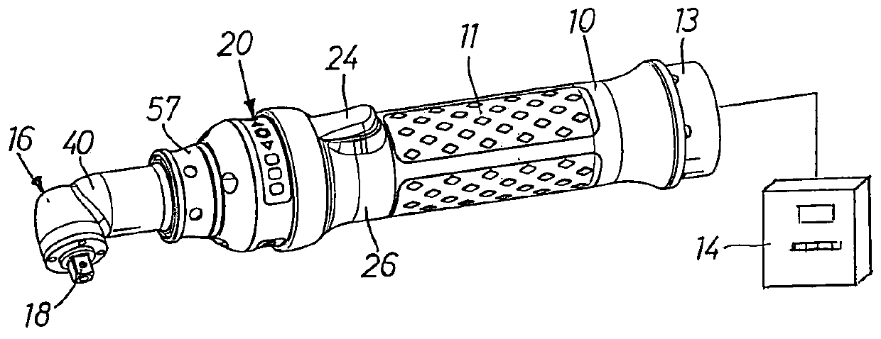
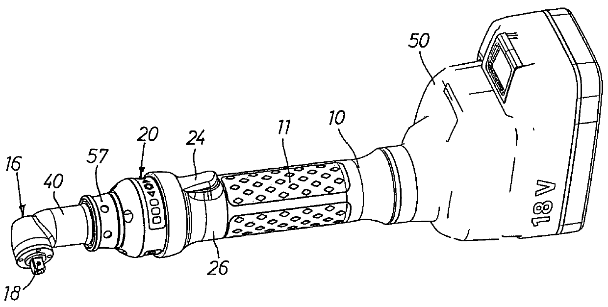
[0021] figure 1 The power wrench shown comprises a cylindrical housing 10 forming a tubular handle 11 and supporting an electric motor, not shown. The housing 10 is provided at its rear end with a connection socket 13 for connecting power and signal transmission cables communicating with a separate programmable operation control unit 14 . The nature and sequence of operations of the control units are of a well-known type and form no part of the present invention. Therefore no further elaboration was given.

[0022] The housing 10 carries at its front end an elbow 16 having a square ended output shaft 18 adapted to carry a nut socket. The output shaft 18 extends in a transverse direction perpendicular to the cylindrical housing 10 and is connected to the electric motor via an angular transmission. The elbow 16 is connected to the housing 10 by a rotary coupling 20 so that the elbow 16 can be set in a plurality of selectable angular positions relative to the housing 10 so tha...


PUM


Abstract

A power wrench comprises a cylindrical housing (10), a motor, and an angle head (16) attached to the housing (10) and supporting an output shaft (18) in a laterally extending position, wherein the angle head (16) is connected to the housing (10) via a swivel coupling (20) so as to enable rotation of the angle head (16) and adjustment of the angular position of the output shaft (18) relative to thehousing (10). A releasable locking device (55) is provided between the angle head (16) and the housing (10) for arresting the angle head (16) in alternative angular positions relative to the housing(10).

Description

technical field [0001] The invention relates to a power wrench, which includes a cylindrical housing, a motor and an elbow, the elbow is supported on the housing and includes a transversely extending output shaft. The housing is understood to be cylindrical as a whole, or in those areas where it is necessary to facilitate the use and action of the turning of the tool elbow. Background technique [0002] In prior art power wrenches of the type described above, handling problems are encountered during the tightening operation of some threaded joints in difficult-to-reach locations. A big reason for this is the orientation of the output shaft relative to the power wrench housing, which means that when trying to access an awkwardly positioned nipple, some part or parts of the wrench housing may come into contact with where the nipple is. contact with the structure, thereby preventing the wrench from reaching the proper working position. [0003] Particularly in battery powered...

Claims


Application Information

Patent Timeline
Patent Type & Authority Applications(China)
IPC IPC(8): B25F3/00B25F5/02B25B23/00
CPCB25F3/00B25F5/02B25B23/0028B25B21/00B25B13/481
Inventor P·L·安德松
Owner ATLAS COPCO INDAL TECHN AB
Why Eureka
Try Eureka