Permanent magnet motor

A permanent magnet motor and magnet technology, applied in electric components, magnetic circuit rotating parts, magnetic circuits, etc., can solve the problem that the magnetic isolation slot cannot take into account the d-axis and q-axis magnetic flux paths, and cannot obtain rotational speed and torque at the same time. problem, to achieve the effect of both output performance and reduction of cogging torque

Active Publication Date: 2020-01-31
ADLEE POWERTRONIC
View PDF7 Cites 0 Cited by
  • Summary
  • Abstract
  • Description
  • Claims
  • Application Information

AI Technical Summary

Problems solved by technology

In addition, the rotor of this patent can also be provided with magnetic isolation slots. However, the magnetic isolation slots of this patent cannot take into account the d-axis and q-axis magnetic flux paths, and the q-axis magnetic flux path is even blocked, so it cannot be obtained at the same time. Better speed and torque

Method used


Image

  • Permanent magnet motor
  • Permanent magnet motor
  • Permanent magnet motor

Examples


Embodiment Construction

[0038] The following examples illustrate possible implementations of the present invention, but are not intended to limit the protection scope of the present invention.

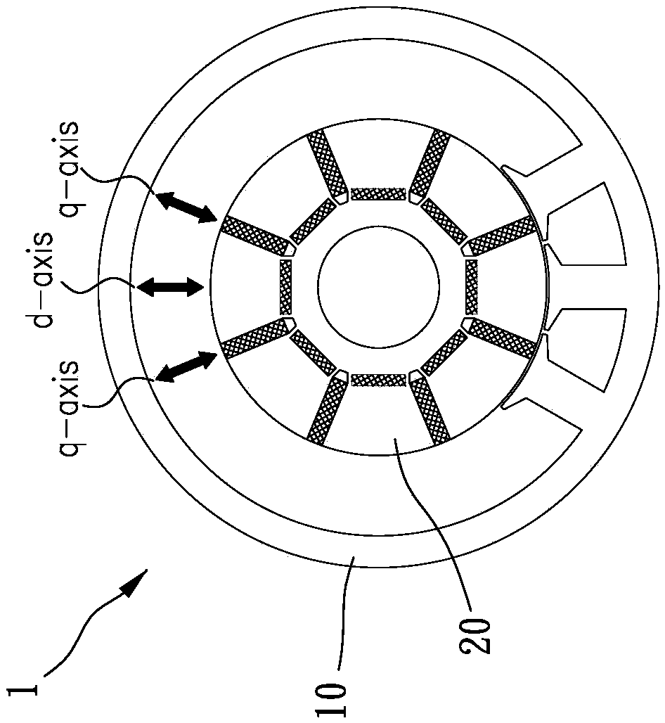
[0039] Please refer to Figures 1 to 6 , which shows a preferred embodiment of the present invention, the permanent magnet motor 1 of the present invention includes a stator 10 and a rotor 20 .

[0040] The stator 10 is provided with a plurality of windings 11 . The rotor 20 is provided with a plurality of magnet placement slots 21 and a plurality of magnetic isolation empty slots 22, and the plurality of magnet placement slots 21 includes a plurality of circumferential magnet placement slots 211 arranged in the circumferential direction and a plurality of radially arranged The width direction magnet placement slots 212, each of the circumferential magnet placement slots 211 and each of the width direction magnet placement slots 212 are arranged alternately in the circumferential direction, and the plurality...


PUM


Abstract

The invention provides a permanent magnet motor. The permanent magnet motor includes a stator which is provided with a plurality of windings, a rotor which is provided with a plurality of magnet placement slots and a plurality of magnetically isolated empty slots. The plurality of magnet placement slots include a plurality of circumferential magnet placement slots which are circumferentially arranged and a plurality of widthwise magnet placement slots which are arranged in the width direction. Each circumferential magnet placement slot and each widthwise magnet placement slot are alternately arranged in the circumferential direction. The plurality of magnetically isolated empty slots are close to the magnet placement slots and distributed in a d-axis magnetic flux path direction of the rotor.

Description

technical field [0001] The invention belongs to the technical field of motors, in particular to a permanent magnet motor. Background technique [0002] In order to meet requirements such as different rotational speeds, loads, and performances, the required characteristics are generally obtained through different arrangement numbers, positions, or angle changes of the magnets in the rotor. In the case of China Taiwan Certificate No. 129116, it has the characteristics of elastic changes. However, the width-wise magnet only provides a magnetic field for a single magnetic pole, so that two pieces of width-wise magnets are required between two adjacent magnetic poles, thus increasing the cost of the magnet. Furthermore, there is a certain distance between the two webs and the magnets, which causes the magnetic pole spread angle of the magnetic poles to be reduced, which is not conducive to the output characteristics of the motor. [0003] U.S. Patent No. 8,044,548 discloses tha...

Claims


Application Information

Patent Timeline
IPC IPC(8): H02K1/27
CPCH02K1/2706
Inventor 朱守昱
Owner ADLEE POWERTRONIC
Why Eureka
Try Eureka