
An inverter control method and device

A control method and a technology of a control device, which are applied in the directions of circuit devices, output power conversion devices, and conversion of AC power input to DC power output, and can solve problems affecting the safe operation of inverters, etc.

Active Publication Date: 2020-10-02
ZHENGZHOU YUTONG BUS CO LTD
View PDF19 Cites 0 Cited by
  • Summary
  • Abstract
  • Description
  • Claims
  • Application Information

AI Technical Summary

Problems solved by technology

[0006] The object of the present invention is to provide an inverter control method and device, which is used to solve the problem in the prior art that the safe operation of the inverter is affected due to the phenomenon of hard switching when controlling the full-bridge inverter

Method used


Image

  • An inverter control method and device
  • An inverter control method and device
  • An inverter control method and device

Examples


Embodiment Construction

[0028] The object of the present invention is to provide an inverter control method and device for solving the problem in the prior art that the safe operation of the inverter is affected due to the phenomenon of hard switching when controlling the full-bridge inverter.

[0029] To achieve the above object, the technical solution provided by the invention is:

[0030] A method for controlling an inverter, comprising the steps of:

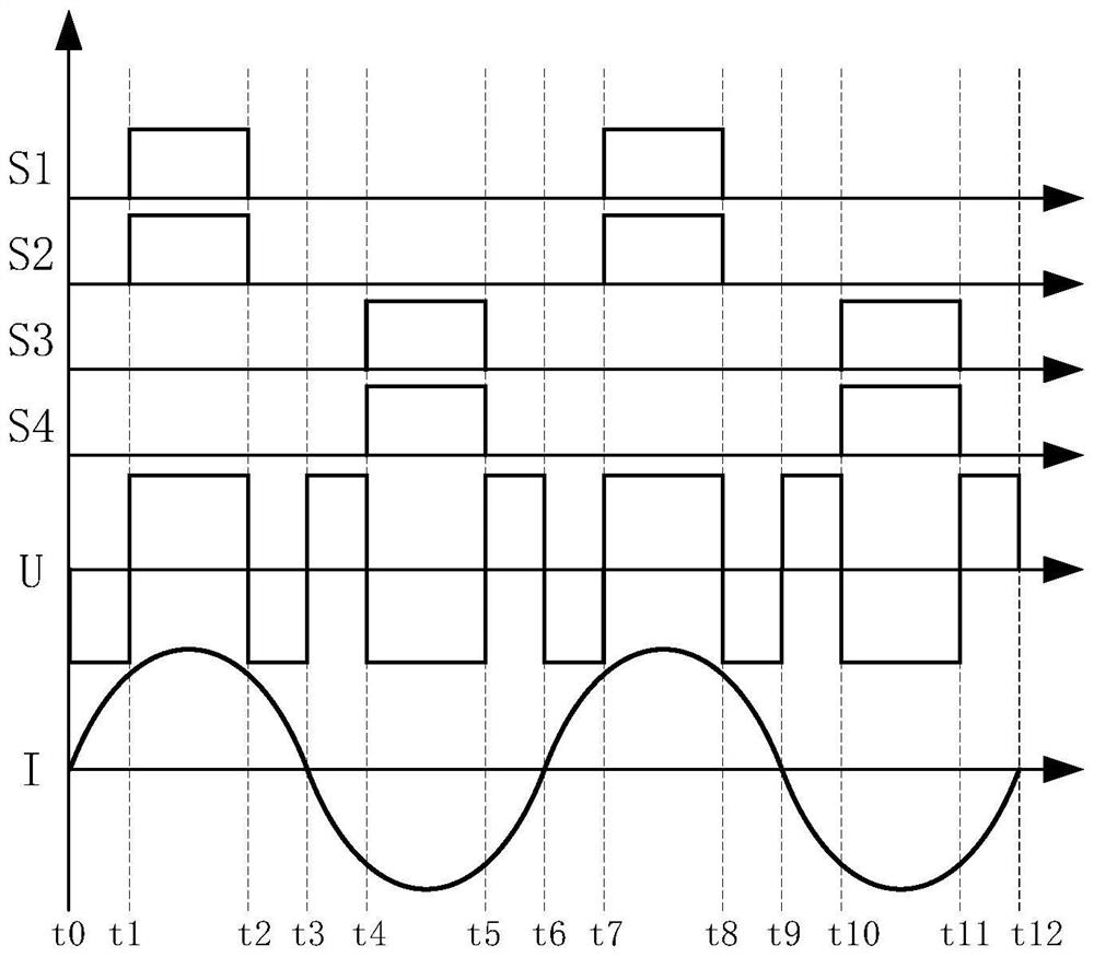
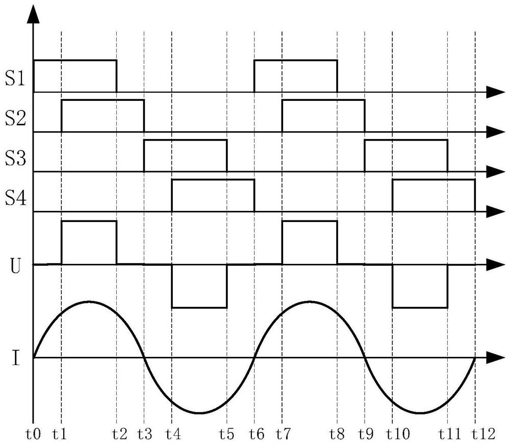
[0031] Control each switching tube of the inverter according to the control sequence of the control cycle;

[0032] Assume that one of the bridge arms of the inverter is the super-forearm, and the other bridge arm is the lagging arm; at the beginning of a control cycle, the first switch tube of the super-forearm is firstly controlled to conduct, and the first switch tube of the super-forearm is turned on. After a set time, the second switching tube of the lagging arm is controlled to be turned on; when the second switching tube of the lagging arm i...


PUM


Abstract

The invention provides an inverter controlling method and device. The control method comprises the steps that each switching tube is controlled according to the control sequence of a control cycle; atthe beginning of a control cycle, firstly the first switching tube of a leading arm is controlled to be turned on, and after the first switching tube of the leading arm is turned on for a first set time, the second switching tube of a lagging arm is controlled to be turned on; when the second switching tube of the lagging arm is turned off, the second switching tube of the leading arm is controlled to be turned on, and after the second switching tube of the leading arm is turned on for the first set time, the first switching tube of the lagging arm is controlled to be turned on; when the first switching tube of the lagging arm is turned off, the control cycle ends; the turn-on time of each switching tube in the same control cycle is the same; and the turn-on time of each switching tube islonger than the first set time. According to the technical scheme provided by the invention, when each switching tube in an inverter is turned off, the voltage and current thereof are zero; and the problem that the safe operation of the inverter is affected by a hard switching phenomenon when the full-bridge inverter is controlled in the prior art is solved.

Description

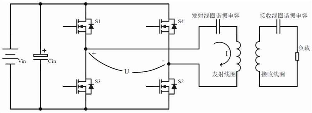
technical field [0001] The invention belongs to the technical field of inverter control, and in particular relates to an inverter control method and device. Background technique [0002] Traditional contact power transmission technology requires wires and frequent plugging and unplugging, which limits the flexibility, safety and convenience of equipment movement, and also affects the aesthetics and cleanliness of the equipment environment; and wireless power transmission technology because of its The advantages of convenient transmission, long transmission distance, high transmission efficiency and less influence by intermediate obstacles have attracted more and more attention. [0003] Wireless power transfer technology is realized based on the principle of electromagnetic induction. The coupling mechanism used in wireless power transfer technology is as follows: figure 1 As shown, it includes a transmitting part and a receiving part, both of which are provided with a coil...

Claims


Application Information

Patent Timeline
Patent Type & Authority Patents(China)
IPC IPC(8): H02M7/5387H02J50/12
CPCH02J50/12H02M7/5387
Inventor 张瑞丰肖兴兴宁小磊张龙飞曹晓鸽章文文
Owner ZHENGZHOU YUTONG BUS CO LTD
Learn More