
Multi-objective optimization-based unmanned vehicle motion planning method

An unmanned vehicle, multi-objective optimization technology, applied in the direction of measuring devices, instruments, surveying and navigation, etc., can solve problems such as difficult to determine the weight

Active Publication Date: 2020-02-04
CENT SOUTH UNIV
View PDF6 Cites 33 Cited by
  • Summary
  • Abstract
  • Description
  • Claims
  • Application Information

AI Technical Summary

Problems solved by technology

However, the traditional path planning method based on randomly scattered points, such as RRT, does not satisfy the vehicle kinematics and dynamics constraints; the traditional trajectory generation method based on curve fitting transforms the multi-objective weighting in the multi-objective optimization problem Target optimization problem, the weight is difficult to determine

Method used


Image

  • Multi-objective optimization-based unmanned vehicle motion planning method
  • Multi-objective optimization-based unmanned vehicle motion planning method
  • Multi-objective optimization-based unmanned vehicle motion planning method

Examples


Embodiment Construction

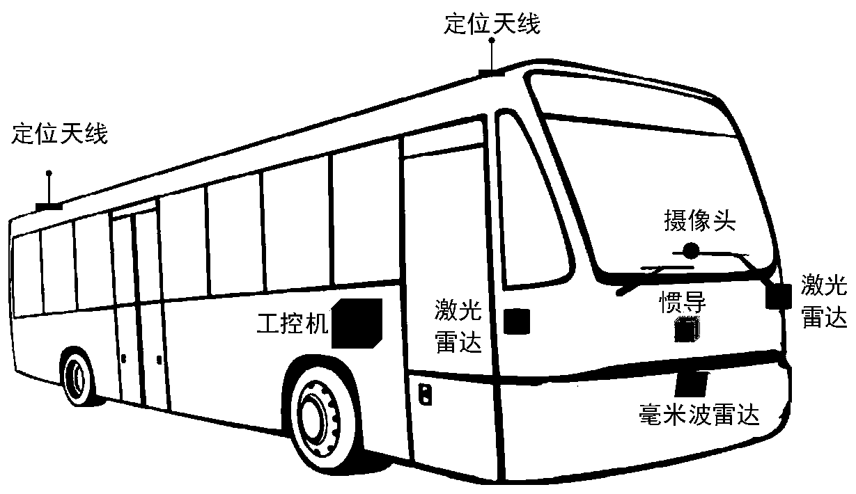
[0055] The present embodiment adopts the intelligent car that length 12m, wide 2.5m bus are refitted, and infrared transceiver, lidar, millimeter-wave radar, camera and GPS / IMU system are housed.

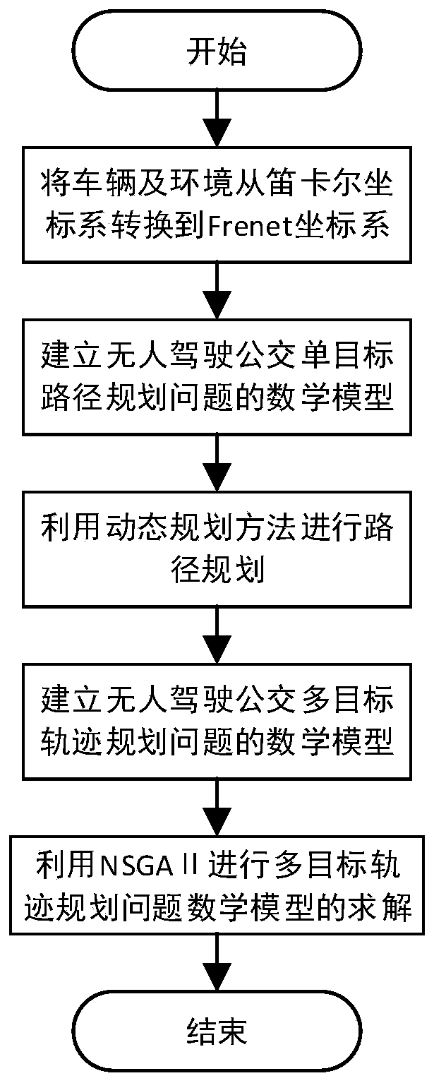
[0056] A multi-objective optimization-based unmanned vehicle motion planning method based on the NSGA II algorithm in an urban road environment, comprising the following steps:

[0057] Step 1: Map the vehicle and the environment from the Cartesian coordinate system to the Frenet coordinate system. The following path planning and trajectory generation are all performed in this coordinate system;

[0058] Step 2: Using the weighted sum of smoothing cost, obstacle cost, and reference line cost as the evaluation index, establish a mathematical model for the multi-objective path planning problem of unmanned vehicles;

[0059] Step 3: use the linear dynamic programming method for path planning, solve the mathematical model of the multi-objective path planning problem, and obtain the path...


PUM


Abstract

The invention discloses a multi-objective optimization-based unmanned vehicle motion planning method. A vehicle and an environment are mapped from a Cartesian coordinate system to a Frenet coordinatesystem. A mathematical model for an unmanned vehicle multi-objective path planning problem is established. Path planning is performed by using a linear dynamic planning method. A track is described byusing a piecewise quintic polynomial, and a mathematical model for an unmanned vehicle multi-objective track generation problem is established by using a minimum track slope, minimum curvature, comfortable riding experience, and a closest distance to a path obtained from linear dynamic planning respectively as optimization objectives, using a location of a piecewise quintic polynomial connectionpoint, a first order derivative, a second order derivative, and a third order derivative as equality constraints, and using a road natural boundary constraint and an obstacle boundary constraint as inequality constraints. An optimal solution of the unmanned vehicle multi-objective track generation problem is obtained. The invention solves a problem that a path obtained by using a random point scatter-based path planning method is difficult to meet a vehicle kinematics constraint.

Description

technical field [0001] The invention belongs to the technical field of intelligent driving and its planning, and in particular relates to a motion planning method for unmanned vehicles based on multi-objective optimization. Background technique [0002] Since its introduction in 1886, the automobile field has developed rapidly, and its technological development and popularization have become an important symbol to measure the degree of modernization and civilization of a country or region. However, with the popularity of cars and the exponential growth of ownership, people are also suffering from serious annoyances caused by worsening traffic jams and accidents. Therefore, intelligent driving technology has received people's attention. In the urban road environment, the driving conditions are relatively simple, and there are maps with higher precision, so it is easier to realize intelligent driving. The 2017 national key research and development plan has clearly listed the...

Claims


Application Information

Patent Timeline
IPC IPC(8): G01C21/34
CPCG01C21/3446
Inventor 余伶俐邵玄雅魏亚东周开军王正久霍淑欣白宇
Owner CENT SOUTH UNIV
Learn More