
cable assembly

A technology of connecting wires and connectors, which is applied in the direction of connection, parts of connecting devices, devices for relieving stress at wire connections, etc. Inconvenience and other issues

Active Publication Date: 2020-11-03
SHANGHAI CHUANGGONG COMM TECH
View PDF7 Cites 0 Cited by
  • Summary
  • Abstract
  • Description
  • Claims
  • Application Information

AI Technical Summary

Problems solved by technology

[0003] Taking the data cable as an example, the wire body at the end of the wire body is often bent during use, and the connector is fixed. The tension caused by the bending of the wire body will cause the wire inside the connector to deform, and it is easy to cause the wire to break after repeated use. , the data line is damaged
Correspondingly, when the interface end is connected to the smart device and put into the bag, the wire body of the interface end is prone to be bent to a large extent, which is easy to damage the interface end and the interface end of the smart device, and affects the electrical connection between the data cable and the smart device. connect
In addition, the direction of the interface end is usually fixed. When users use smart devices, they sometimes hold them horizontally and sometimes vertically. The interface end with a fixed direction makes it inconvenient for users to use.
[0004] To sum up, the connecting wires in the prior art have the defects that the connecting parts are easily damaged (due to the bending of the wire body) and inconvenient for users to use (due to the fixed direction of the interface end)

Method used


Image

  • cable assembly
  • cable assembly

Examples


Embodiment Construction

[0047] The present invention is further illustrated below by means of examples, but the present invention is not limited thereto within the scope of examples.

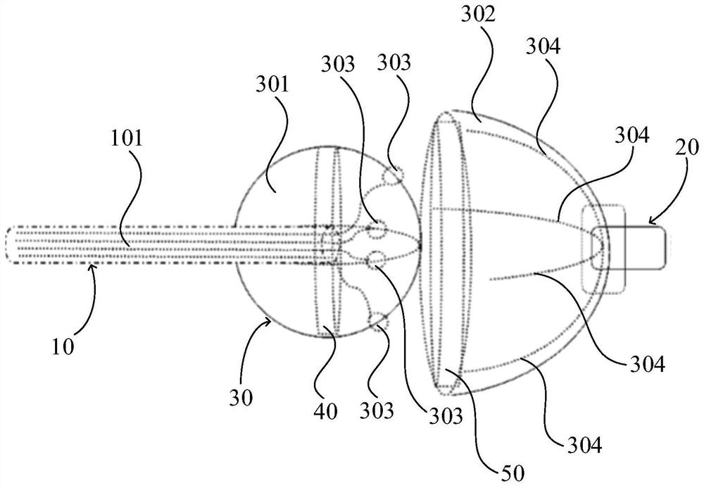
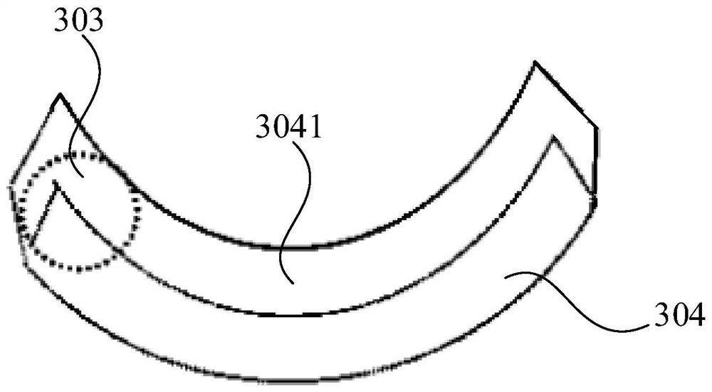
[0048] This embodiment discloses a connecting wire 101 assembly, such as Figure 1-2 As shown, the connecting line 101 assembly includes a line body end 10, an interface end 20 and a connector 30 connected between the line body end 10 and the interface end 20, and the connector 30 includes a first connecting body 301, a conductor 303, a second connecting body 302 and connecting rail 304. Wherein, the first connecting body 301 has a first end and a second end along the extending direction of the line body in the line body end 10, the first end is connected to the line body end 10, and one end of the line body end 10 is connected to the first connecting body 301 Extend into the inside of the first connecting body 301 . The conductor 303 is embedded on the outer wall of the second end, and the conductor 303 is connected...


PUM


Abstract

The invention discloses a connecting wire assembly. The connecting wire assembly comprises a wire body end, an interface end and a connecting piece connected between the wire body end and the interface end, wherein the connecting piece comprises a first connecting body, a conductor, a second connecting body and a connecting rail; the first connecting body is provided with a first end and a secondend in the extending direction of a wire body in the wire body end, the first end is connected to the wire body end, and one end of the wire body end extends into the first connecting body; the conductor is embedded in the outer wall surface of the second end and is connected to the wire body; the second connecting body is provided with an accommodating cavity used for accommodating at least partof the first connecting body at the side facing the second end, and the side, which deviates from the second end, of the second connecting body is connected to the interface end; and the connecting rail is arranged on the inner wall surface of the accommodating cavity and extends in the extending direction of the second connecting body, the end, which faces the interface end, of the connecting rail is connected to a welding plate in the interface end, and the conductor is arranged on the connecting rail in a sliding mode so as to enable the first connecting body to slide relative to the secondconnecting body. According to the connecting wire assembly, the influence of the bending tension of the wire body can be reduced or counteracted, and the damage of the connecting wire assembly can bereduced or prevented.

Description

technical field [0001] The invention relates to the field of mobile terminals, in particular to a connecting line assembly. Background technique [0002] Connection lines, such as power lines and data lines, usually include a line body end, an interface end, and a connector connected between the line body end and the interface end. Wherein, the connecting piece is usually fixed between the line body end and the interface end, and the outside of the connecting piece is wrapped with insulating rubber. [0003] Taking the data cable as an example, the wire body at the end of the wire body is often bent during use, and the connector is fixed. The tension caused by the bending of the wire body will cause the wire inside the connector to deform, and it is easy to cause the wire to break after repeated use. , the data cable is damaged. Correspondingly, when the interface end is connected to the smart device and put into the bag, the wire body of the interface end is prone to be b...

Claims


Application Information

Patent Timeline
Patent Type & Authority Patents(China)
IPC IPC(8): H01R13/56H01R13/58
CPCH01R13/562H01R13/58
Inventor 王鑫
Owner SHANGHAI CHUANGGONG COMM TECH
Learn More