A distributed fault diagnosis system and method for transmission lines
What is AI technical title?
AI technical title is built by Patsnap AI team. It summarizes the technical point description of the patent document.
A fault diagnosis system and transmission line technology, applied in transmission systems, digital transmission systems, fault locations, etc., can solve problems such as difficult coordination and expansion of single applications, continuous deployment obstacles, reliability and stability effects, etc.
Active Publication Date: 2021-09-10
NARI TECH CO LTD +1
View PDF5 Cites 0 Cited by
Summary
Abstract
Description
Claims
Application Information
AI Technical Summary
This helps you quickly interpret patents by identifying the three key elements:
Problems solved by technology
Method used
Benefits of technology
Problems solved by technology
The excellent performance of distributed traveling waves in transmission line fault location has led to the rapid development of distributed traveling waves. There are many manufacturers of transmission line fault diagnosis and monitoring terminals, and the diagnostic and positioning function modules have been moved to the central station. The central station needs to have horizontal expansion capabilities. Simplify application deployment, and support the requirements of uninterrupted massive big data storage and analysis of original messages. The traditional architecture adopts a monolithic application architecture. Complex monolithic applications themselves are obstacles to continuous deployment. When resource conflicts exist between different modules, monolithic The application is difficult to coordinate and expand, which has a greater impact on its reliability and stability
Method used
Image
Click on the blue label to locate the original text in one second.
Reading with bidirectional positioning of images and text.
Examples
Embodiment 1
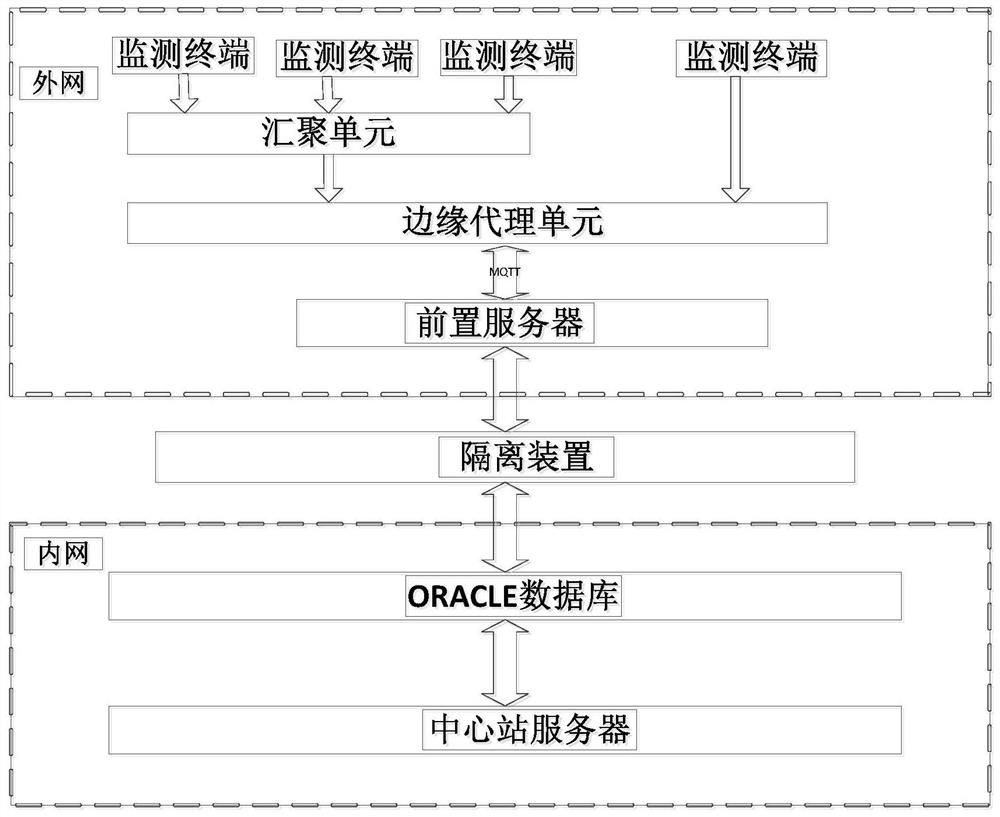
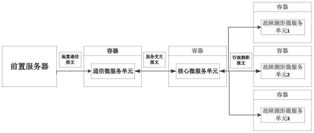
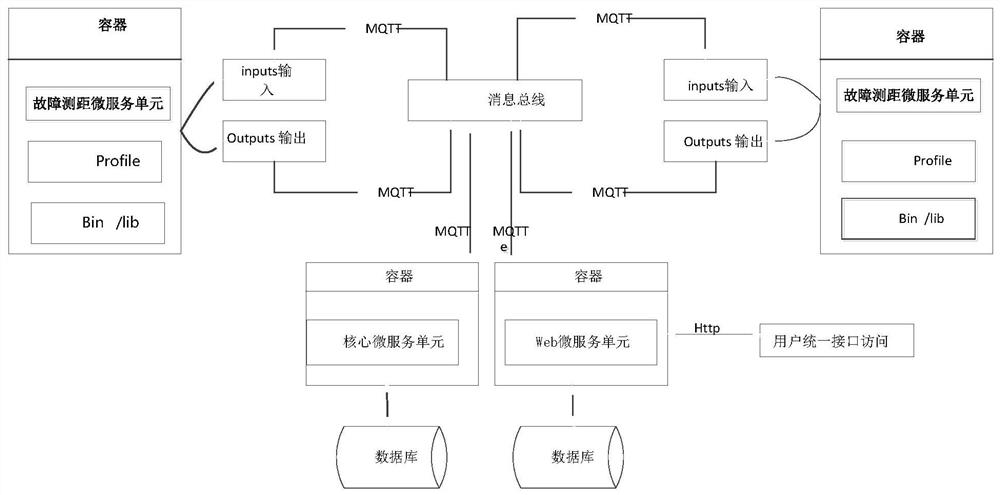
[0060] Such as figure 1 As shown, the embodiment of the present invention provides a distributed fault diagnosis system for transmission lines, including a monitoring terminal, a front server, and a central station server, and the central station server includes a communication microservice unit, a core microservice unit, and a fault location microservice unit;
[0061] In the specific application process of the transmission line distributed fault diagnosis system in the embodiment of the present invention, the monitoring terminal is deployed on various poles and towers, and is used to collect data such as traveling wave current, fault current traveling wave data, and clock data;
[0062] Such as Figure 2-4 As shown, the front-end server receives the data message (such as device traveling wave current data message) sent by the monitoring terminal, and stores it in a database, such as an oracle database; in a specific implementation manner of an embodiment of the present inve...
Embodiment 2
[0094] The difference between the embodiment of the present invention and embodiment 1 is:
[0095] A converging unit and an edge agent unit connected in sequence are arranged between the monitoring terminal and the front-end server;
[0096] The convergence unit is also connected to the monitoring terminal, so that multiple monitoring terminals converge to the convergence unit;
[0097]The edge proxy unit is also connected to the front-end server to realize protocol conversion and interconnection.
[0098] An isolation device is provided between the fault diagnosis unit and the front-end server, which mainly realizes the physical isolation of the monitoring terminal and the business system (that is, the communication micro-service unit, the core micro-service unit and the fault ranging micro-service unit) to prevent illegal links Access through the intranet.
[0099] Example 2
[0100] An embodiment of the present invention provides a distributed fault diagnosis method for...
PUM
Abstract
The invention discloses a distributed fault diagnosis system and method for transmission lines. The distributed fault diagnosis system includes a monitoring terminal, a front server and a central station server. The central station server includes a communication microservice unit, a core microservice unit and a fault distance measurement microservice unit; the front-end server receives the data message sent by the monitoring terminal and stores it in the database; the communication microservice unit reads the data message from the database document and form a file; the core microservice unit receives the interaction message sent by the communication microservice unit, finds out the corresponding fault location microservice unit based on the ID information in the interaction message, and obtains from the communication microservice unit The file sent to the fault distance measurement microservice unit; the fault distance measurement microservice unit completes the fault diagnosis based on the received file. The invention can greatly shorten the access time of fault distance measuring terminals (that is, fault distance measuring micro service units) of different manufacturers to the system, and improve the efficiency of operation and maintenance.
Description
technical field [0001] The invention belongs to the technical field of power grid operation and maintenance, and in particular relates to a distributed fault diagnosis system and method for transmission lines. Background technique [0002] Overhead transmission lines have many points, long lines, wide areas, and complex network structures. They are distributed in the wild with harsh environments, causing great difficulties for equipment inspections. During actual operation, they often suffer from natural disasters (lightning strikes, rainstorms, Extremely bad weather such as heavy snow, strong wind, bird damage and other factors) and external damage (various constructions, traffic accidents, human-made theft, etc.), cause the grounding short circuit tripping of the line, or even the line is broken, causing the line to be paralyzed and causing a large area The power outages have brought certain impacts on the stability, safety, economy, efficiency and high-quality operation of ...
Claims
Application Information
Patent Timeline
Application Date:The date an application was filed.
Publication Date:The date a patent or application was officially published.
First Publication Date:The earliest publication date of a patent with the same application number.
Issue Date:Publication date of the patent grant document.
PCT Entry Date:The Entry date of PCT National Phase.
Estimated Expiry Date:The statutory expiry date of a patent right according to the Patent Law, and it is the longest term of protection that the patent right can achieve without the termination of the patent right due to other reasons(Term extension factor has been taken into account ).
Invalid Date:Actual expiry date is based on effective date or publication date of legal transaction data of invalid patent.

