Vertical roller mill and operation method therefor

A technology of vertical roller mill and operation method, applied in grain processing and other directions, can solve the problems of difficult drying and pulverizing high-moisture coal, etc., and achieve the effect of economical and stable operation

Inactive Publication Date: 2020-02-04
KAWASAKI HEAVY IND LTD
View PDF8 Cites 0 Cited by
  • Summary
  • Abstract
  • Description
  • Claims
  • Application Information

AI Technical Summary

Problems solved by technology

However, conventional vertical roller mills are mostly used to pulverize high-grade coal such as bituminous coal with a degree of coalification, and it is difficult to efficiently dry it under the same operating conditions as conventional vertical roller mills for high-grade coal. crush high moisture coal

Method used


Image

  • Vertical roller mill and operation method therefor
  • Vertical roller mill and operation method therefor
  • Vertical roller mill and operation method therefor

Examples


experiment example

[0093] Hereinafter, Experimental Example 1, Comparative Experimental Example 1, and Experimental Example 2 of the present invention will be described. Table 1 below shows the supply start inlet temperature, supply start outlet temperature, and running outlet temperature (all of which are control target values) among the operating conditions of the vertical roller mill 1 in Experimental Example 1 and Comparative Experimental Example 1. Each experiment was carried out on a vertical roller mill for testing which is smaller than the actual machine.

[0094] [Table 1]

[0095] .

experiment example 1

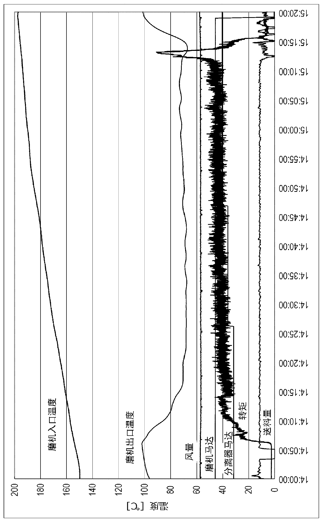
[0097] In Experimental Example 1, hot gas was supplied to the mill inlet 72 of the vertical roller mill for testing at a certain flow rate, and it took one hour of preheating time to preheat the vertical roller mill 1 until the mill inlet temperature was 150°C (controlled target value). The mill outlet temperature was about 100°C when the mill inlet temperature was 150°C, and this mill outlet temperature sufficiently exceeded 65°C as the feed start outlet temperature. After preheating the vertical roller mill 1 in this way, the mill motor 51 and the separator motor 81 are rotated to start supply of lignite with a moisture content of 60 to 64%. After starting the supply of lignite, adjust the temperature of the hot gas supplied to the mill inlet 72 to between 150 and 320°C so that the temperature at the mill outlet is maintained at 70°C (control target value) and adjust the temperature from the mill outlet. 71 The flow rate of the discharged mill exhaust. The flow rate of the...

experiment example 2

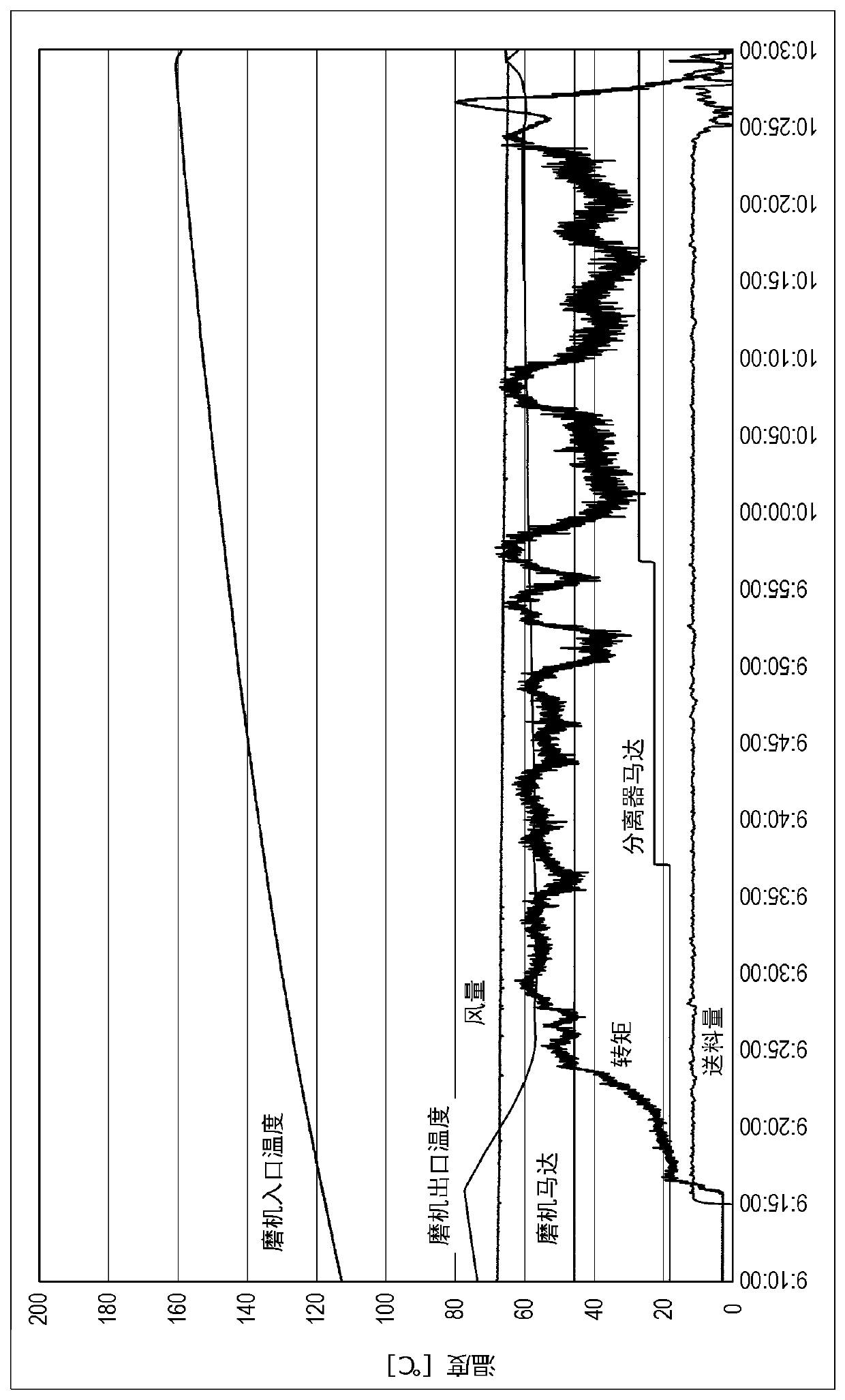
[0109] In Experimental Example 2, in order to find an appropriate range of the inlet temperature at the start of supply, the temperature at the inlet of the mill was changed while the temperature at the outlet of the mill was maintained at 60°C (control target value), and the temperature of the mill motor 51 was measured. torque value. In addition, the operating conditions of the vertical roller mill 1 of Experimental Example 2 are that the supply flow rate of the hot gas is constant, the rotational speed of the mill motor 51 is constant, and the rotational speed of the separator motor 81 is performed within a fluctuation range of about 10% of the rated rotational speed. Adjustment, the supply of lignite is constant.

[0110] Figure 6 The torque value of the mill motor 51 of Experimental Example 2 and the temporal change of the mill inlet temperature are shown. like Figure 6 As shown, the torque value of the mill motor 51 of Experimental Example 2 fluctuates unstably when...


PUM


Abstract

By supplying hot gas to a mill inlet in a vertical roller mill, a prescribed pre-heating time is applied and pre-heating occurs so as to achieve a prescribed supply start inlet temperature at which the discharge gas temperature at the mill outlet is at least 65DEG C and the hot gas temperature at the mill inlet is 150-250 DEG C. After pre-heating, high moisture content coal supply to a rotating table is started and at least either the flow rate or the temperature of the hot gas supplied to the mill inlet is adjusted such that the temperature of the discharge gas at the mill outlet is maintained at 65-100 DEG C.

Description

technical field [0001] The invention relates to a vertical roller mill for crushing low-grade high-moisture coal and an operation method of the vertical roller mill. Background technique [0002] Low-grade coal such as lignite is said to account for half of the world's coal deposits, and is attracting attention as a promising energy resource. However, low-grade coal has a problem of reduced energy efficiency as a fuel due to its high water content. In recent years, low-grade coal with a moisture content of about 35-40% has been treated without changing the texture, but for low-grade high-moisture coal with a moisture content of more than 50% (hereinafter referred to as high-moisture coal), in order to improve energy efficiency Improvements such as reducing the moisture content or crushing are expected to be carried out in order to improve transport efficiency. Therefore, a technique for efficiently drying and pulverizing high-moisture coal is required. [0003] Convention...

Claims


Application Information

Patent Timeline
Patent Type & Authority Applications(China)
IPC IPC(8): B02C4/02
CPCB02C4/02
Inventor 安藤文典堀田滋宫川伸一
Owner KAWASAKI HEAVY IND LTD
Why Eureka
Try Eureka