Bidirectional optical transceiver

Inactive Publication Date: 2007-05-03
SAMSUNG ELECTRONICS CO LTD
View PDF9 Cites 12 Cited by
  • Summary
  • Abstract
  • Description
  • Claims
  • Application Information

AI Technical Summary

Benefits of technology

[0011] It is, therefore, an object of the present invention to provide an economical

Problems solved by technology

Briefly, the bidirectional optical transceiving module of Siemens Corp. includes three lenses, making its structure complicated and increasing its cost.
On the other hand, the bidirectional optical transceiving module of Lucent Technologies Inc. includes two lenses, but the optical axes of an optical fiber and a filter are not easy to arrange and an expensive aspherical lens is additionally required to minimize the occurrence of

Method used


Image

  • Bidirectional optical transceiver
  • Bidirectional optical transceiver
  • Bidirectional optical transceiver

Examples


Example

[0023] An embodiment of the present invention will now be described in detail with reference to the annexed drawings. For the purposes of clarity and simplicity, a detailed description of known functions and configurations incorporated herein has been omitted for conciseness.

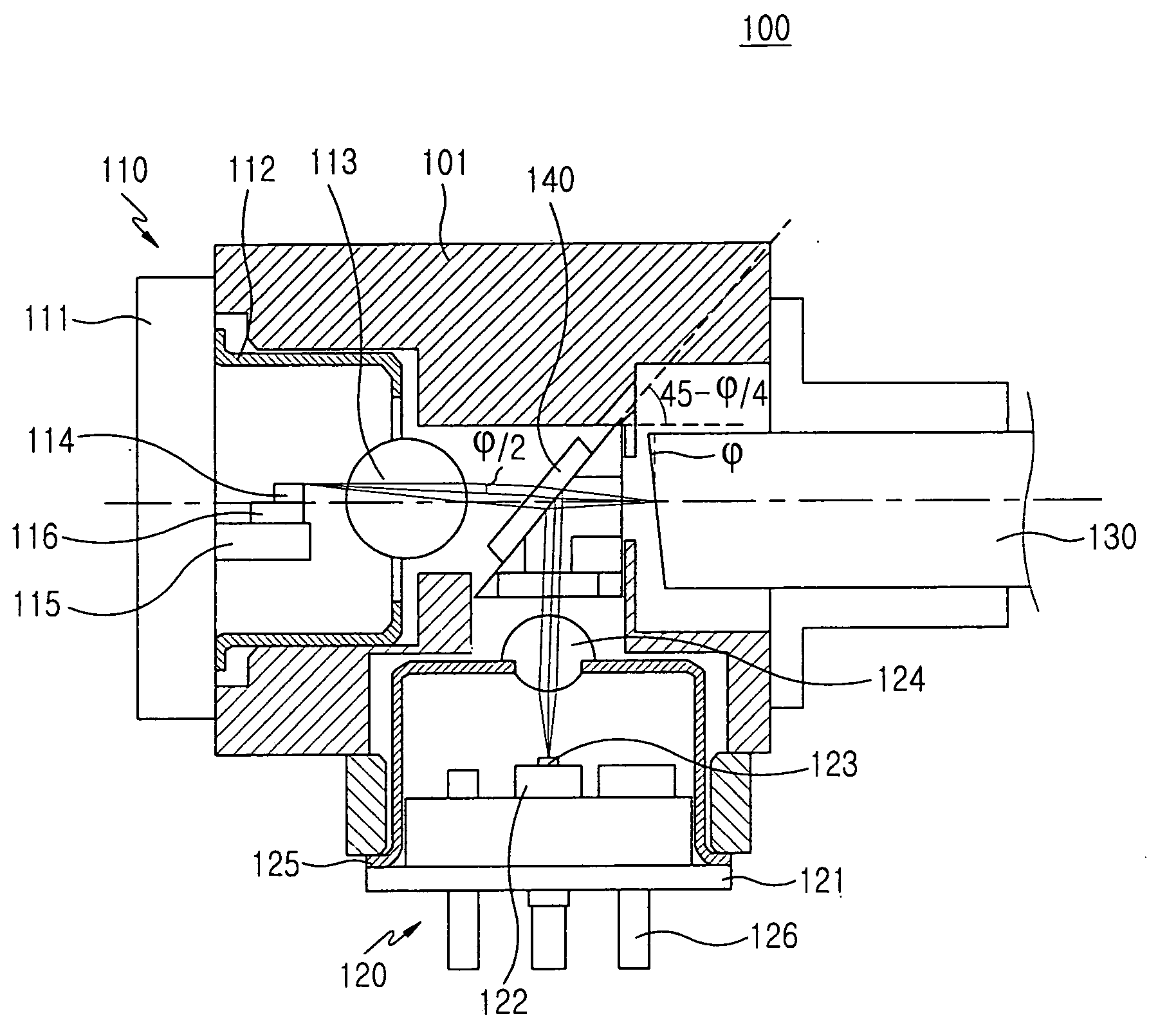
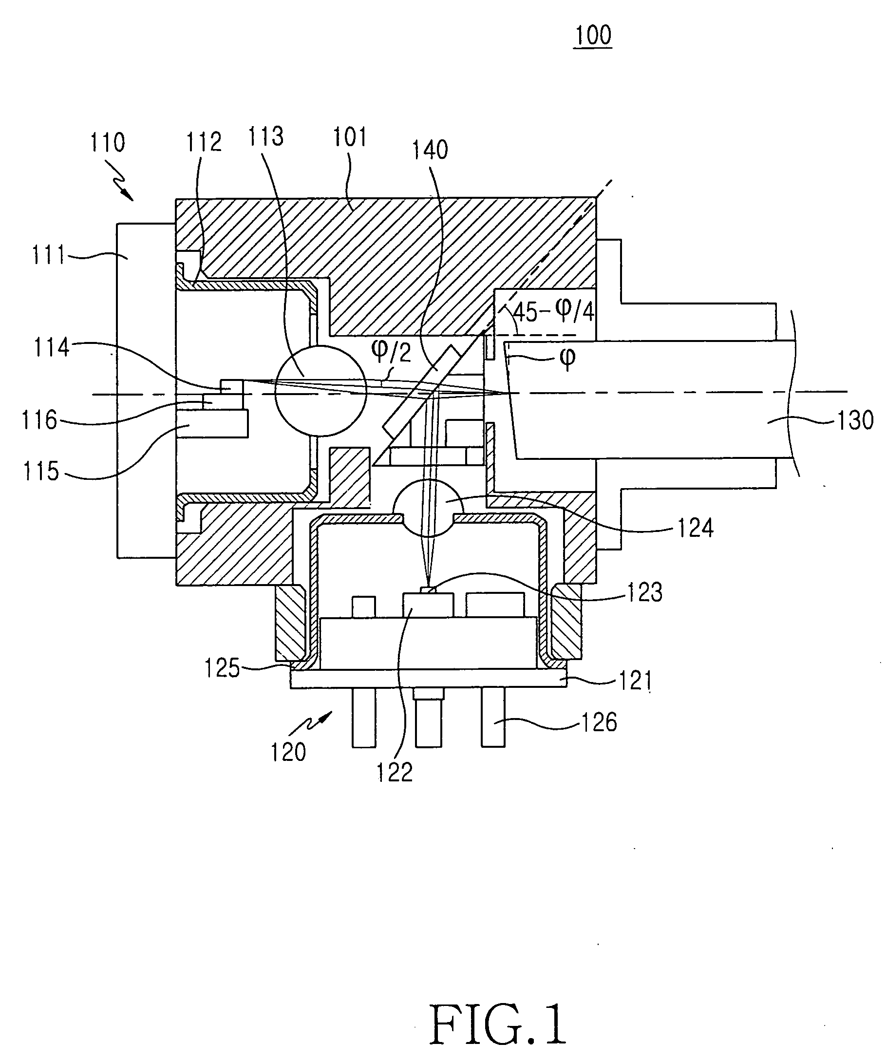
[0024]FIG. 1 illustrates a bidirectional optical transceiver 100 according to an embodiment of the present invention. As shown, the bidirectional optical transceiver 100 includes a wavelength-selecting filter 140 for separating the traveling paths of a first optical signal and a second optical signal, a transmitting module 110 for generating the first optical signal, a receiving module 120 for detecting the second optical signal, and an optical fiber 130 for inputting and outputting the first optical signal and the second optical signal. Note that the transmitting module 110 and the receiving module 120 have TO-CAN structures.

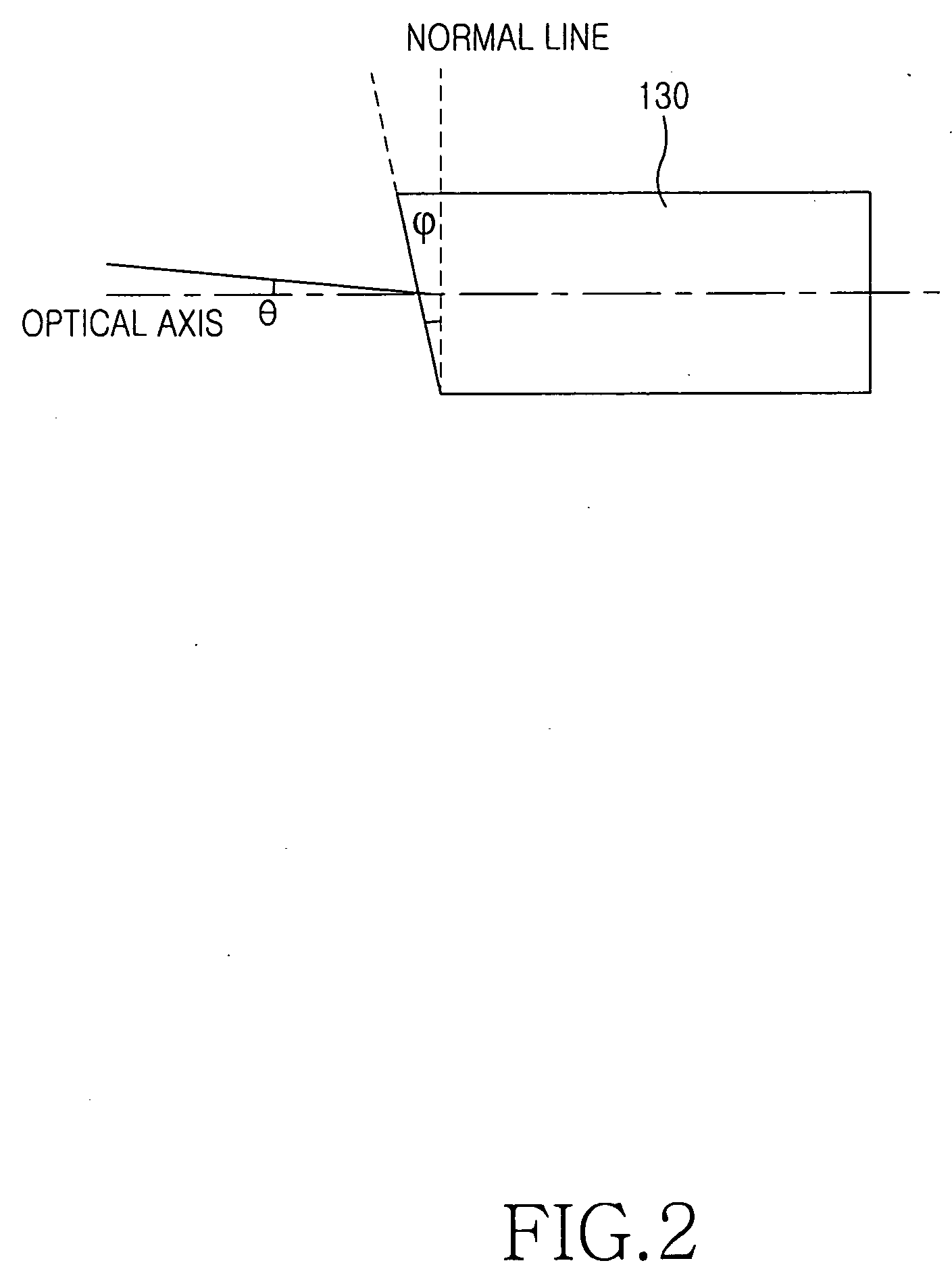
[0025] The optical fiber 130 includes a face that is opposite to the wavelength-selec...


PUM


Abstract

A bidirectional optical transceiver includes a wavelength-selecting filter, an optical fiber, a transmitting module, and a receiving module. The wavelength-selecting filter is placed on an optical axis, passes a first optical signal therethrough, and reflects a second optical signal perpendicularly to the traveling path of the second optical signal. The optical fiber has a face that is opposite to the wavelength-selecting filter and is inclined at an angle of φ with respect to a normal line perpendicular to the optical axis. The transmitting module is placed on the optical axis in opposition to the optical fiber with respect to the wavelength-selecting filter and has a light source for generating the first optical signal and outputting the generated first optical signal to the wavelength-selecting filter at an inclined angle with respect to the optical axis.

Description

CLAIM OF PRIORITY [0001] This application claims priority under 35 U.S.C. § 119 to an application entitled “Bidirectional Optical Transceiver” filed in the Korean Intellectual Property Office on Oct. 31, 2005 and assigned Serial No. 2005-103237, the contents of which are incorporated herein by reference. BACKGROUND OF THE INVENTION [0002] 1. Field of the Invention [0003] The present invention generally relates to an optical transceiver, and in particular, to an optical transceiver used in a bidirectional optical communication field. [0004] 2. Description of the Related Art [0005] With an increase demand in transmission of high-quality broadcasting, Internet data, and video conferences at individual homes, the establishment of Fiber to the Home (FTTH) networks using optical fibers is being actively carried out. [0006] An economical optical communication solution, i.e., a 1.25 Gbps Ethernet Passive Optical Network (EPON), includes a single central office (an Optical Line Terminal: OLT...

Claims


Application Information

Patent Timeline
IPC IPC(8): G02B6/36
CPCG02B6/4214G02B6/4246G02B6/0026G02B7/027
Inventor BAEK, JAE-MYUNGPARK, JOONG-WAN
Owner SAMSUNG ELECTRONICS CO LTD
Why Eureka
Try Eureka