Cryostat having a magnet coil system, which comprises an LTS section and a heatable HTS section

a technology of magnet coils and cryostats, which is applied in the manufacture/treatment of superconducting magnets/coils, superconductor devices, and reradiation. it can solve the problems of ceramic material sealing failure and conductor degradation, and achieve the effect of facilitating sample placement, reducing the risk of helium tank convection around the hts section, and reducing the risk of re-radiation

Inactive Publication Date: 2013-03-26
BRUKER BIOSPIN
View PDF8 Cites 1 Cited by
  • Summary
  • Abstract
  • Description
  • Claims
  • Application Information

AI Technical Summary

Benefits of technology

[0014]It should be noted that the temperature TL of the largest portion of the liquid helium in the helium tank of the cryostat can, in accordance with the invention, be present at a temperature which is equal to or less than the λ point temperature of 2.2 K. It is only necessary for the HTS to be locally subjected to a sufficient degree of warmth. A temperature of TL of 2.2 K or less is even advantageous for particularly stable operation of the LTS section, in particular to minimize mechanical deformations due to temperature differences. However, most importantly, a temperature TL of less than 2.2 K increases the current carrying capacity as well as the critical magnetic field strength of the associated cooled LTS sections.
[0027]In an additional preferred embodiment of the cryostat in accordance with the invention, the helium tank has means to minimize convection of helium about the HTS section. The means are e.g. mechanical barriers disposed on a surface of the HTS section or proximate thereto to prevent or curtail the flow of helium on the surface of the HTS section or on the surfaces of components which are coupled thermally to the HTS section. The reduced convection reduces the flow of heat into the liquid helium caused by the heating means and also thereby reduces the cooling power of the liquid helium on the HTS section. This makes the cryostat more economical and more stable.

Problems solved by technology

A sealing of the ceramic material is to no avail.
Since HTS is a ceramic material and therefore brittle, the HTS ruptures locally in response to the pressure, thereby resulting in degradation of the conductor.

Method used


Image

  • Cryostat having a magnet coil system, which comprises an LTS section and a heatable HTS section
  • Cryostat having a magnet coil system, which comprises an LTS section and a heatable HTS section
  • Cryostat having a magnet coil system, which comprises an LTS section and a heatable HTS section

Examples


first embodiment

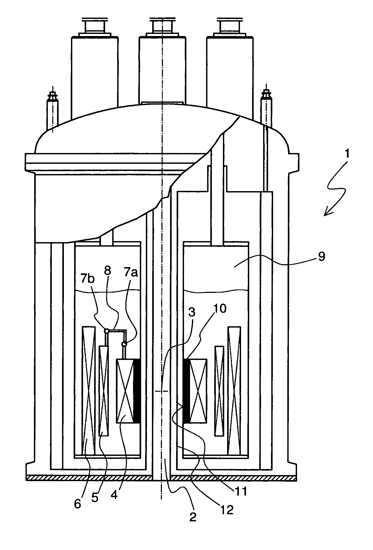
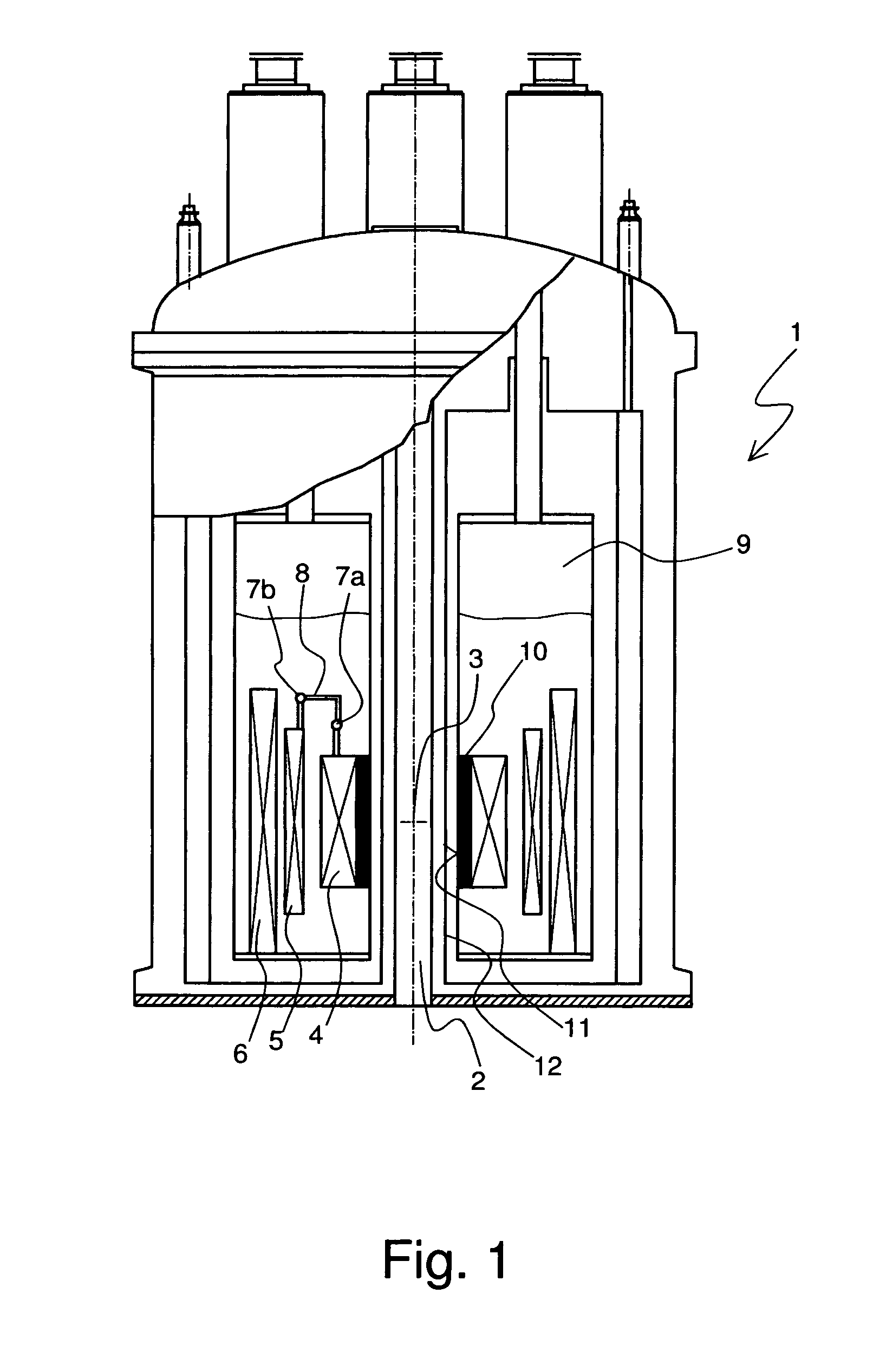
[0034]FIG. 1 schematically shows a cryostat 1 in accordance with the invention. The cryostat 1 has a room temperature bore 2 in which an investigational volume 3 for a sample is provided. The investigational volume 3 is located in the center of a magnetic coil system, which constitutes three solenoid-shaped coil section 4, 5, 6. The magnet coil system produces a homogeneous magnetic field B0 in the investigational volume 3. The radially innermost coil section 4 has a wounding made from high temperature superconductor (HTS). The middle coil section 5 is wound with Nb3Sn wire and the outer most coil section 6 is wound with NbTi wire. The coil sections 5, 6 therefore represent low temperature superconductor (LTS) coil sections. The coil sections 4, 5, 6 are electrically connected to each other in series, as is shown in an exemplary fashion by means of superconducting joints 7a and 7b. At joint 7a, the high HTS material of the HTS coil section 4 is connected to an adaptor section 8 made...

third embodiment

[0038]FIG. 3 shows a cryostat 1 in accordance with the invention. The HTS section 4 is connected to another thermal contact 31. This thermal contact is fed through the floor 32 of the helium tank 9 and is connected to the radiation shield 12 at the bottom region thereof. The radiation shield 12 has a temperature TS of approximately 40 K and can therefore give enough heat into the HTS section 4 in order to prevent the penetration of superfluid into the HTS section 4. The heat input can, for example, be easily adjusted by means of the diameter of the thermal contact 31. The thermal contact 31 is preferentially thermally insulated, e.g. by means of a plastic jacket, along its entire length up to the ends.

[0039]In addition, means 33 are provided on the upper edge of the HTS section 4 to prevent helium from flowing between the thermal contact 31 and the wall 11 of the helium tank 9. Towards this end, the means 33 are ring-shaped. Alternative thereto, the function of such means can also b...

fourth embodiment

[0040]FIG. 4 shows a cryostat 1 in accordance with the invention. The HTS section 4 is not only actively heated by means of thermal contacts rather also actively heated by an electrical heater 41. Towards this end, a heating coil (made e.g. of copper) runs on the surface of or inside the HTS section 4. The heating power is adjusted in such a fashion that the desired temperature TH of the HTS section 4 results. In accordance with the invention, a temperature sensor can be provided on or in the HTS section 4 in order to monitor TH. In general, a constant heating current is utilized. For simplification, the electrical leads and the current supply for the electrical heater 41 are not shown.

[0041]A jacket 42 made from a three-layer epoxy resin, which thermally insulates the HTS section 4 from the environment and also serves for mechanical separation, additionally surrounds the HTS section 4. The jacketing 42 thereby also includes the joint 7a so that the jacket 42 encloses all the HTS ma...


PUM

PropertyMeasurementUnit
temperatureaaaaaaaaaa
temperature TLaaaaaaaaaa

Abstract

A cryostat (1) with a magnet coil system including superconductors for the production of a magnet field B0 in a measuring volume (3) has a plurality of radically nested solenoid-shaped coil sections (4, 5, 6) and which are electrically connected in series, at least one of which being an LTS section (5, 6) with a conventional low temperature superconductor (LTS) and at least one of which being an HTS section (4) including a high temperature superconductor (HTS), wherein the magnet coil system is located in a helium tank (9) of the cryostat (1) along with liquid helium at a helium temperature TL<4 K. The apparatus is characterized in that heating means are provided which always keep the HTS at an increased temperature TH>TL and TH>2.2 K. The cryostat in accordance with the invention can maintain the HTS section over a long period of time in a reliable manner.

Description

[0001]This application is the national stage of PCT / EP2007 / 001927 filed on Mar. 7, 2007 and also claims Paris Convention priority to DE 10 2006 012 506.1 filed Mar. 18, 2006.BACKGROUND OF THE INVENTION[0002]The invention concerns a cryostat having a magnetic coil system including superconducting materials for generation of a magnetic field B0 within a measurement volume, the magnet system having a plurality of radially nested solenoid-shaped coil sections connected in series at least one of which is an LTS section of a conventional low temperature superconductor (LTS) and with at least one HTS section of a high temperature superconductor (HTS), wherein the magnet coil system is located in a helium tank of the cryostat having liquid helium at a helium temperature TL<4 K.[0003]Cryostats of this kind are e.g. disclosed in DE 10 2004 007 340 A1.[0004]By way of example, nuclear magnetic resonance systems, in particular spectrometers, require very strong, homogenous and stable magnetic...

Claims


Application Information

Patent Timeline
Patent Type & Authority Patents(United States)
IPC IPC(8): H01F6/04H01F6/06G01V3/00
CPCH01F6/04
Inventor ROTH, GERHARDLAUSCH, AXEL
Owner BRUKER BIOSPIN
Why Eureka
Try Eureka