Fastening unit for fastening a clamping element to a unit

A technology for fixing units and components, applied in the direction of threaded fasteners, transmission components or ropes or cables for pulleys, connecting components, etc., to achieve the effect of simple use

Active Publication Date: 2020-02-04
SIEMENS AG
View PDF5 Cites 2 Cited by
  • Summary
  • Abstract
  • Description
  • Claims
  • Application Information

AI Technical Summary

Problems solved by technology

Furthermore, for example springs are used in series, but these also have serious disadvantages

Method used


Image

  • Fastening unit for fastening a clamping element to a unit
  • Fastening unit for fastening a clamping element to a unit
  • Fastening unit for fastening a clamping element to a unit

Examples


Embodiment Construction

[0045] Preferred embodiments of the present invention will be described below with reference to the drawings.

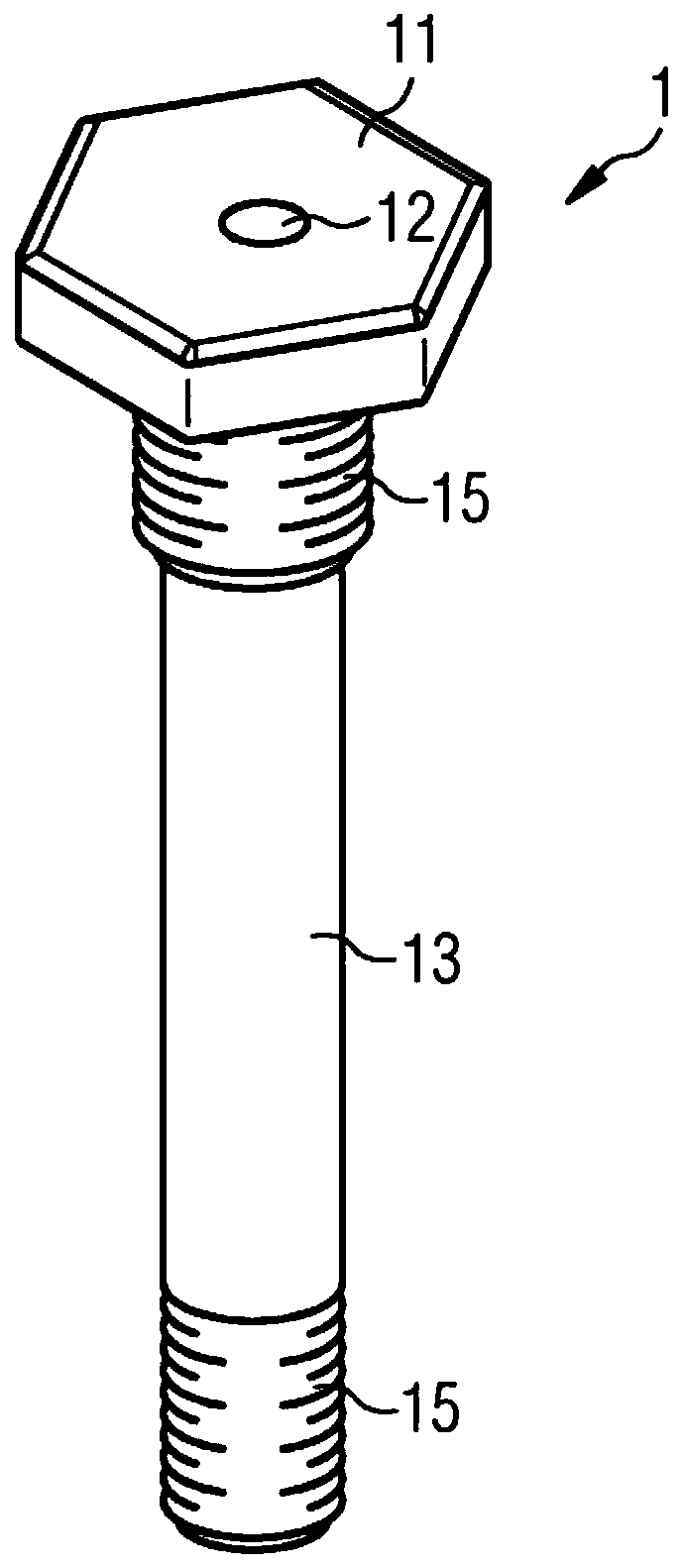
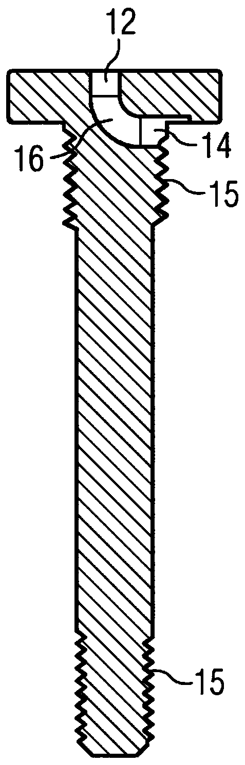
[0046] figure 1A fastening unit 1 is shown, which consists of two subunits 11 , 13 . The upper subunit 11 may be called a head, and the lower subunit 13 may be called a stem. The fixing unit can be produced by means of a 3D printing process or other manufacturing processes. The subunits 11, 13 have openings 12, 14, respectively.

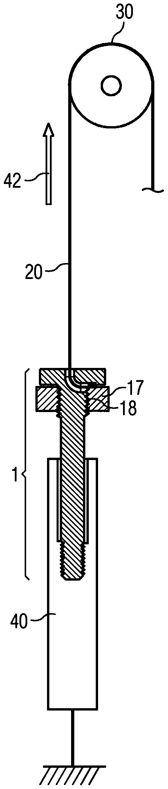
[0047] For example, the head 11 has several edges and is designed flat. The shaft 13 is arranged below the head 11 and is designed in the shape of a thin stick. Furthermore, the shank 13 has a threaded section 15 . For example, the external thread 15 is arranged on the end region of the shank 13 . The shank 13 can correspondingly be inserted into the internal thread 18 of the counter piece 17 . The fastening unit 1 can be, for example, a bolt.

[0048] Between the two openings 12 , 14 , a channel 16 extends continuously from the fir...


PUM


Abstract

The invention relates to a fastening unit (1) for fastening a clamping element (20) to a unit (30), comprising a head (11) having at least one first opening (12), a shank (13) having at least one second opening (14) and at least one external thread (15), and a channel (16), the channel (16) extending at least partially along the shank (13) from the at least one first opening (12) in the head (11)along the head (11) to the at least one second opening (14) in the shank (13), wherein the at least one external thread (15) and the channel (16) are each designed to hold the clamping element (20). The invention also relates to a corresponding system operated by a clamping element.

Description

[0001] 1. Technical field [0002] The invention relates to a fastening unit for fastening a tensioning element to the unit. The invention also relates to a corresponding tensioning element drive system. [0003] 2. Background technology [0004] Tensioner drive systems ("tendon-driven systems") are becoming more and more important. Such systems are provided in the area of ​​robots and mechanisms. For example, tension element-driven robotic units are known which have a body element which simulates the musculoskeletal system. Tensioning element drive systems usually have an actuator which pulls the tensioning element or applies tension thereto. Through force, the actuator also applies force to the joint. In other words, force is transmitted from the actuator to the joint via the tensioning element. However, a single tensioning element can only exert force in one direction. [0005] According to the prior art, therefore, two drive units are arranged for each degree of freed...

Claims


Application Information

Patent Timeline
Patent Type & Authority Applications(China)
IPC IPC(8): F16G11/04F16G11/10F16B33/02F16B35/04
CPCF16G11/044B25J9/1045F16B33/02F16B35/041F16B35/06F16G11/101F16H19/0622F16H2019/0695
Inventor G.巴赫梅尔I.维特托利亚斯W.佐尔斯C.巴赫曼G.派斯
Owner SIEMENS AG
Why Eureka
Try Eureka