
Bird repelling device for agriculture

A technology for birds and agriculture, applied in the field of bird repelling in farmland, can solve the problems of high cost and waste of energy, and achieve the effect of repelling birds.

Inactive Publication Date: 2020-02-07
天门元淼农业产业化发展有限公司
View PDF1 Cites 6 Cited by
  • Summary
  • Abstract
  • Description
  • Claims
  • Application Information

AI Technical Summary

Problems solved by technology

A kind of bird repelling device for power plants in the above-mentioned patent has the following disadvantages: this device plays the role of repelling birds through the pull-out bird repellent storage cabinet and the action of sonic noise, but this device needs chemical reagents and electric energy to drive unit, which is expensive and wastes energy

Method used


Image

  • Bird repelling device for agriculture
  • Bird repelling device for agriculture
  • Bird repelling device for agriculture

Examples


Embodiment 1

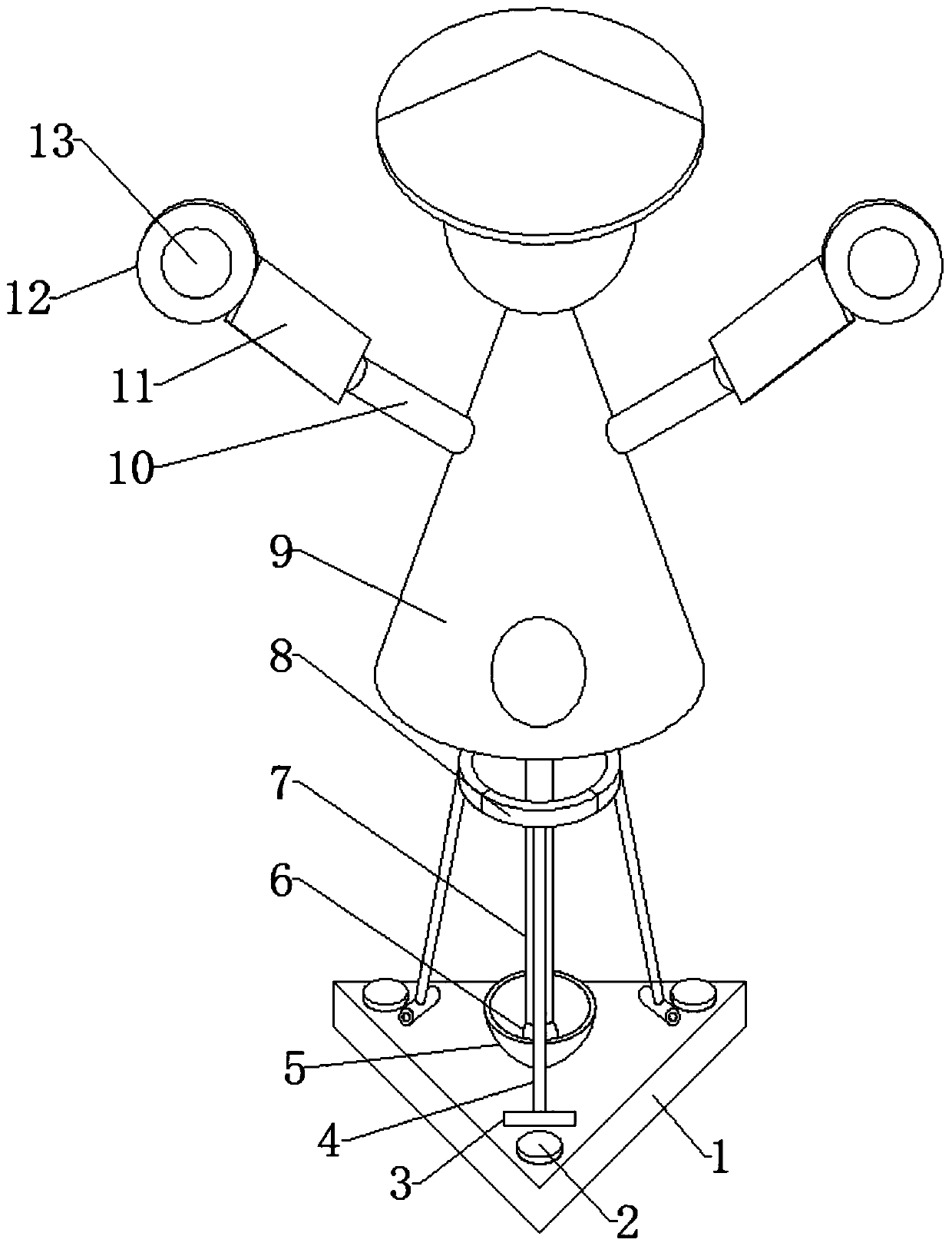
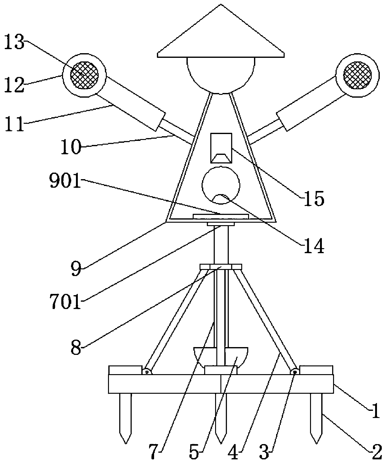
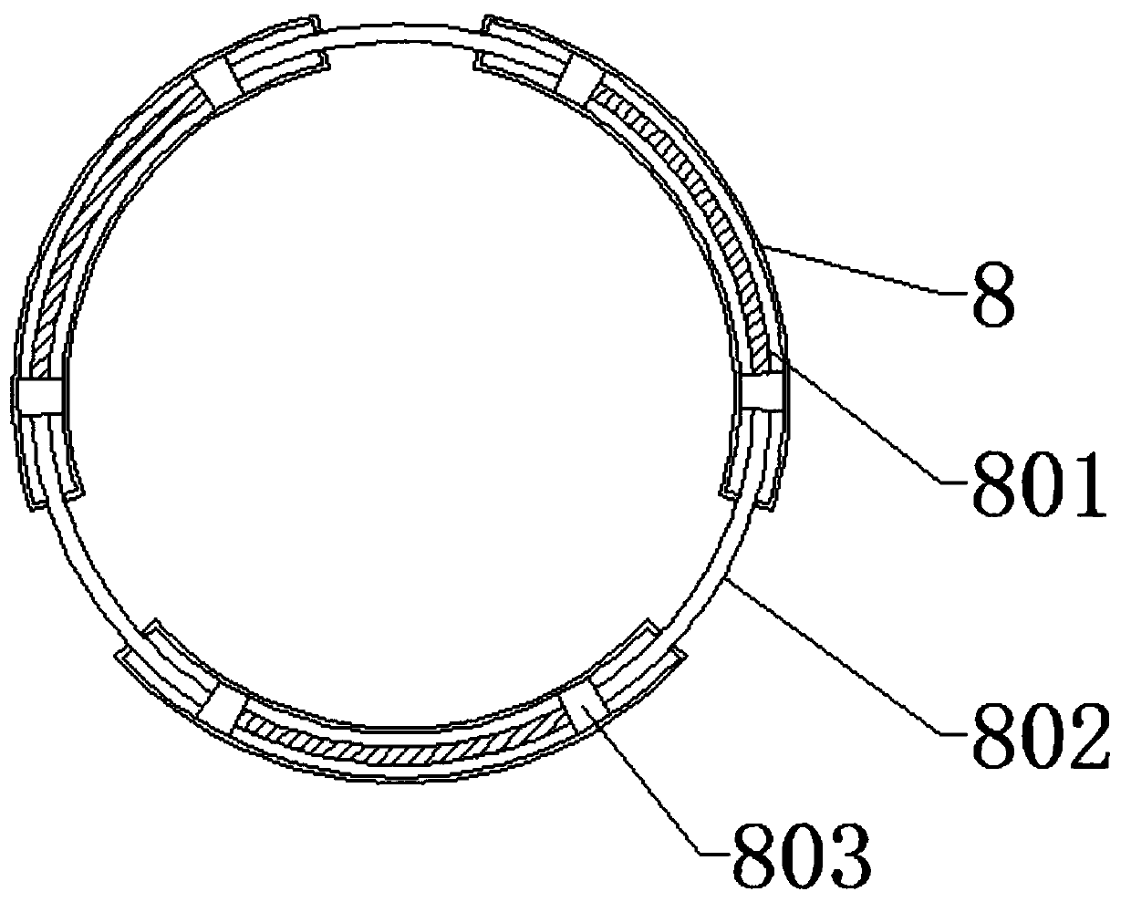
[0026] refer to Figure 1-3 , an agricultural bird repelling device, comprising a bottom plate 1, three rotating shafts 3 are bonded to the top of the bottom plate 1, a rotating rod 4 is bonded to the outer wall of the rotating shaft 3, and a fixed shaft is bonded to the top of the bottom plate 1. Body 5, the middle part of the top of the fixed body 5 is provided with a circular groove, the material of the fixed body 5 is iron, the fixed body 5 is provided with a magnetic ball 6 at the bottom of the circular groove, the magnetic ball The top of the ball 6 is bonded with a connecting rod 7, the top of the connecting rod 7 is bonded with a rotating block 701, and the top of the rotating block 701 is rotatably connected with a main body 9. When the main body 9 is blown by the wind, the main body 9 drives The connecting rod 7 shakes, the magnetic ball 6 and the fixed body 5 are adsorbed, the connecting rod 7 drives the connecting ring 8 to open, and the elastic rope 801 pulls the ...

Embodiment 2

[0033] refer to Figure 4 , an agricultural device for repelling birds. Compared with Embodiment 1, in this embodiment, in order to make the effect of repelling birds better, the top of the main body 9 is bonded with a cap, and the bottom of the cap is two Sides are all bonded with bells 16.

[0034] Working principle: When in use, the base 1 is fixed on the ground through the fixing nails 2. When the main body 9 is blown by the wind, the main body 9 drives the connecting rod 7 to shake, the magnetic ball 6 and the fixed body 5 are adsorbed, and the connecting rod 7 drives the connecting ring 8 Open, the elastic rope 801 pulls the sliding block 803, and the main body 9 returns to an upright state, thereby causing the main body 9 to swing and play the role of driving birds. Thereby can make solar panel 13 receive solar energy, make accumulator 901 charge, when lighting 14 shines at night to attract mosquitoes, mosquitoes fly upwards, thereby enter in collecting box 15, can dri...


PUM


Abstract

The invention discloses a bird repelling device for agriculture, comprising a base plate. Three rotary shafts are fixedly connected to the top end of the base plate; rotary rods are fixedly connectedto the outer walls of the rotary shafts respectively; a fixed member made of iron is fixedly connected to the top end of the base plate, a circular groove is formed in the middle of the top end of thefixed member, and the fixed member is provided with a magnetic ball at the bottom end of the circular groove; a connecting rod is fixedly connected to the top end of the magnetic ball, a rotary blockis fixedly connected to the top end of the connecting rod, and a body is rotationally connected to the top end of the rotary block; a connecting ring is fixedly connected to the top ends of the rotary rods, two sides of the connecting ring are provided with first through holes, and two slide blocks are arranged between the inner walls of the two sides of the connecting ring. Compared with devicesin the prior art, the bird repelling device has the advantages that bird repelling is achieved by driving the body by wind force, and mosquito trapping is achieved through lamps which light at nightunder action of solar energy.

Description

technical field [0001] The invention relates to the technical field of farmland bird repelling, in particular to an agricultural bird repelling device. Background technique [0002] Preventing birds and insects from invading crops in agriculture is a problem that farmers will consider. Usually farmers will set up scarecrows in the fields, but the scarecrows are fixed on the ground. After a long time, the birds will not be afraid of the scarecrows after they get used to it, so It does not play a role in repelling birds. [0003] After searching, the Chinese patent application No. 201821408487.7 discloses a bird repelling device for power plants, including a seat, a housing, a motor, a circuit control cabinet, a pull-out bird repellent storage cabinet and an infrasonic transmitter. A kind of bird repelling device for power plants in the above-mentioned patent has the following disadvantages: this device plays the role of repelling birds through the pull-out bird repellent sto...

Claims


Application Information

Patent Timeline
Patent Type & Authority Applications(China)
IPC IPC(8): A01M29/06A01M29/16A01M1/04
CPCA01M1/04A01M29/06A01M29/16
Inventor 朱元波
Owner 天门元淼农业产业化发展有限公司
Learn More