Automatic feeding device for screw rod machining

An automatic feeding and screw technology, which is applied in the direction of thread cutting device, thread feeding device, metal processing equipment, etc., can solve the problems affecting product quality, high labor intensity of employees, and affecting production safety, so as to improve processing speed and processing quality effect

Pending Publication Date: 2020-02-07
苏州施普曼精密制造科技有限公司
View PDF0 Cites 2 Cited by
  • Summary
  • Abstract
  • Description
  • Claims
  • Application Information

AI Technical Summary

Problems solved by technology

At present, the loading, feeding, positioning, grinding feeding and unloading of CNC centerless grinding machines need to be completed manually. The labor productivity is low, and the labor intensity of employees is high. Monotonous and repetitive operations are likely to cause fatigue and affect production safety.
In addition, the manual positioning is inaccurate, which affects the quality of the product

Method used


Image

  • Automatic feeding device for screw rod machining
  • Automatic feeding device for screw rod machining
  • Automatic feeding device for screw rod machining

Examples


Embodiment 1

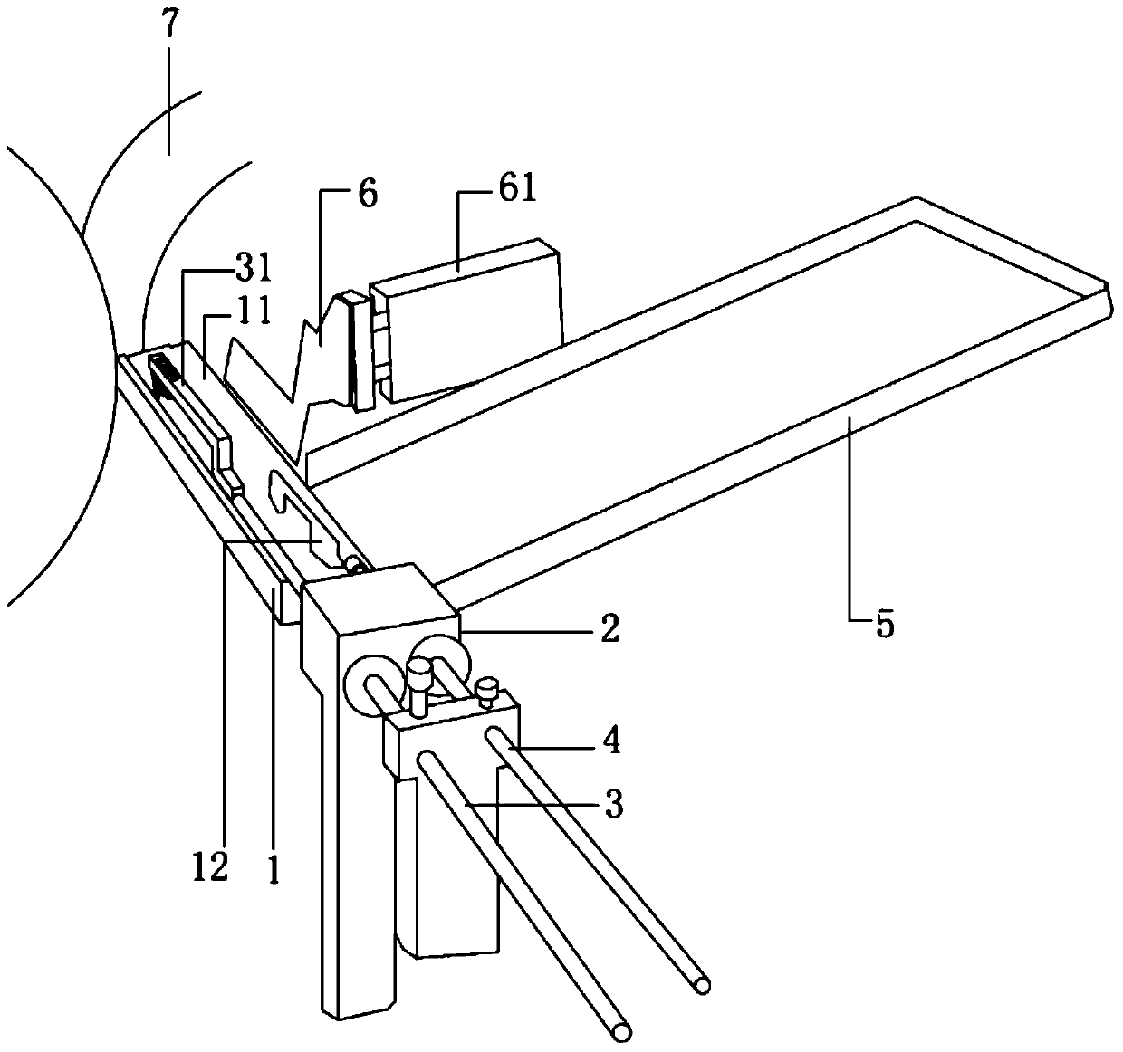
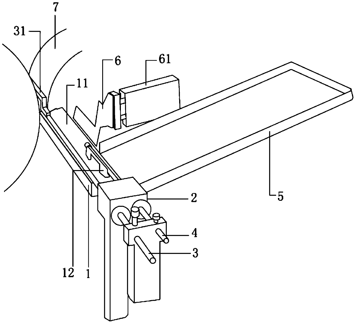
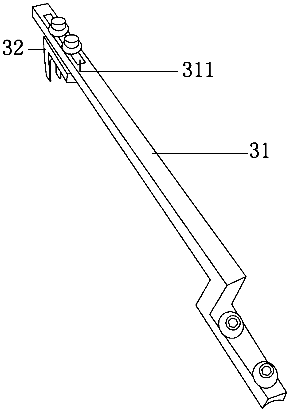
[0023] see Figure 1 to Figure 3 , the figure shows an automatic feeding device for screw mandrel processing provided by Embodiment 1 of the present invention, including: a feeding table 1, a mounting frame 2, a first push rod 3, a second push rod 4, and a feeding tray 5 and the pushing plate 6, one end of the length direction of the feeding table 1 is against the grinder 7, the feeding table 1 is arranged perpendicular to the grinding machine 7, the installation frame 2 is fixedly installed on the other end of the length direction of the feeding table 1, and the first push rod 3 and the second push rod 4 pass through the mounting frame 2, the first push rod 3 and the second push rod 4 are arranged along the length direction of the loading table 1, the first push rod 3 and the second push rod 4 are arranged in parallel, the second push rod 3 The end of a push rod 3 is provided with a pusher clip 31, and the end of the pusher clip 31 is provided with a limit block 32, and the f...

Embodiment 2

[0031] see Figure 1 to Figure 3 , the figure shows an automatic feeding device for screw mandrel processing provided by Embodiment 2 of the present invention. This embodiment further makes the following technical solutions as improvements on the basis of the above embodiments: the first The side of the first push rod 3 is higher than the side of the second push rod 4 , and the contact surface between the table 11 and the first push rod 3 is an arc surface.

[0032] In order to prevent the unprocessed screw rod and the processed screw rod from falling into the unloading device when the pusher plate pushes the unprocessed screw rod, the table of the workbench is set so that the table on the side of the first push rod is higher than that of the second The table on one side of the push rod acts as a barrier to the unprocessed screw rod.

Embodiment 3

[0034] see Figure 1 to Figure 3 , the figure shows an automatic feeding device for screw mandrel processing provided by Embodiment 3 of the present invention. On the basis of the above embodiment, this embodiment further makes the following technical solutions as improvements: the blocking block 12 and The contact surface of the screw rod is an arc surface.

[0035] In order to make the surface of the blocking block better adhere to the surface of the screw rod and make the second push rod more smooth when pushing the screw rod, the contact surface between the blocking block and the screw rod is an arc-shaped surface.


PUM


Abstract

The invention provides an automatic feeding device for screw rod machining. The automatic feeding device comprises a feeding table, a mounting frame, a first push rod, a second push rod, a feeding disc and a pushing plate, wherein one end of the feeding table in the length direction abuts against a grinding machine, and the mounting frame is fixedly mounted at the other end of the feeding table inthe length direction; the first push rod and the second push rod are arranged on the mounting frame in a penetrating mode and arranged in the length direction of the feeding table; a pushing clamp isarranged at the end of the first push rod, and a limiting block is arranged at the end of the pushing clamp; the feeding disc is obliquely arranged on one side of the feeding table, and a screw rod is placed in the feeding disc; a stop block corresponding to the feeding disc in position is arranged on the table top of the feeding table, and the pushing plate and the feeding disc are arranged on the same side of the feeding table; and the pushing plate is pushed by a driving device to move in the vertical direction of the length direction of the feeding table. According to the automatic feeding device for screw rod machining, the screw rod can be accurately and efficiently fed into the grinding machine, and the machining speed and machining quality of the screw rod are greatly improved.

Description

technical field [0001] The invention relates to a feeding device, in particular to an automatic feeding device for screw rod processing. Background technique [0002] The screw generally refers to the ball screw. Ball screws are ideal for converting rotary motion to linear motion, or linear motion to rotary motion. Ball screw is the most commonly used transmission element in tool machinery and precision machinery. Its main function is to convert rotary motion into linear motion, or convert torque into axial repeated force. It also has high precision, reversibility and high precision. Features of efficiency. Due to its small frictional resistance, ball screws are widely used in various industrial equipment and precision instruments. [0003] The screw rod needs to be ground during the processing process, and the grinding is generally completed by a CNC centerless grinding machine. At present, the loading, feeding, positioning, grinding feeding and unloading of CNC centerl...

Claims


Application Information

Patent Timeline
IPC IPC(8): B23G11/00B23G1/36B23G1/44B24B5/35
CPCB23G1/36B23G1/44B23G11/00B24B5/355
Inventor 王范
Owner 苏州施普曼精密制造科技有限公司
Why Eureka
Try Eureka