Positioning adjusting device with ultrahigh precision

A positioning adjustment and precision technology, applied in the field of ultra-high-precision positioning adjustment devices, can solve the problems of reduced service life, no positioning reference, inaccurate measurement and reading, etc., and achieve the effect of improving service life and reducing heat

Pending Publication Date: 2020-02-07
JIANGSU JITRI JINGKAI HIGH VALUE MFG CO LTD
View PDF1 Cites 0 Cited by
  • Summary
  • Abstract
  • Description
  • Claims
  • Application Information

AI Technical Summary

Problems solved by technology

However, in practice, it is found that this technology still has the following defects: figure 1 As shown, there is no positioning reference in the radial direction when installing the actuator: only rely on the contact surface of the head part of the preload mechanism and the inner end surface of the housing to locate and lock in the radial direction and axial direction, while the contact surface of the head part of the preload mechanism And the internal end surface of the housing provides friction to fix the actuator in the radial direction. At this time, the friction fixation cannot ensure that the axis of the actuator is concentric with the force direction of the tool, and the actuator is subjected to bending moments during cutting, which reduces its service life; like figure 2 As shown, the displacement sensor is not positioned in the axial direction: factors such as vibration, impact, and temperature rise in the processing process will easily cause the position of the displacement sensor to change, making the measurement reading inaccurate; the displacement sensor is installed on the end cover in the prior art solution In the through hole, the outer diameter of the displacement sensor and the "shaft hole" of the inner diameter of the through hole are installed together. Since the high-precision sensor cannot be installed by tapping with a mallet, the displacement sensor and the through hole are clearance fit. Under this fit, there is only a small amount of friction on the displacement. The sensor is fixed in the axial direction, and the position of the displacement sensor will change during the handling of the processing device and normal processing, resulting in inaccurate readings

Method used


Image

  • Positioning adjusting device with ultrahigh precision
  • Positioning adjusting device with ultrahigh precision
  • Positioning adjusting device with ultrahigh precision

Examples


Embodiment Construction

[0034] The preferred embodiments of the present invention will be described in detail below with reference to the accompanying drawings, so that the advantages and features of the present invention can be more easily understood by those skilled in the art, so as to make a clearer and clearer definition of the protection scope of the present invention.

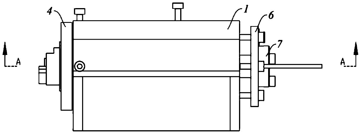
[0035] Please refer to Figure 3 ~ Figure 6 , The present invention includes:

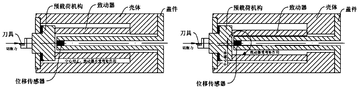
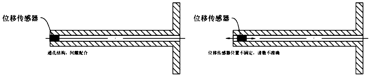
[0036] An ultra-high-precision positioning adjustment device includes: a base 1, an actuator and a displacement sensor 3 installed in the base 1, and a pre-loading mechanism installed on one side of the base 1, the pre-loading mechanism For applying a preload to the actuator, and the displacement sensor 3 for detecting the vibration displacement of the actuator;

[0037] In this embodiment, the actuator is a piezoelectric ceramic 2 with a circular cross-section, the preload mechanism is a flexible hinge 4, and a spacer 5 is also fixed in the base 1. The fl...


PUM


Abstract

The invention discloses a positioning adjusting device with ultrahigh precision. The device comprises a piezoelectric ceramic which is annular in cross section, a flexible hinge, a pad block and a displacement sensor, wherein annular grooves matched with the outer diameter of the piezoelectric ceramic are formed in the flexible hinge and the pad block correspondingly, the annular grooves are usedfor limiting and supporting the end part of the piezoelectric ceramic to perform axial and radial positioning on the piezoelectric ceramic, an adjusting support is also included, a fixing cover is mounted on the adjusting support, a column part is arranged in the middle of the fixing cover, the column part makes contact with the end part, penetrating through the piezoelectric ceramic, of a displacement sensor, and the column part is used for axially positioning the displacement sensor. According to the device, through the above mode, the axial and radial positioning of the piezoelectric ceramic and the displacement sensor can be realized, and the axial line of the displacement sensor is ensured to be parallel with the axial line of the piezoelectric ceramic, so that the detection precisionof the displacement sensor is improved.

Description

Technical field [0001] The invention relates to the technical field of ultra-high-precision machining, in particular to an ultra-high-precision positioning adjustment device. Background technique [0002] Due to advances in precision motion control and measurement / high-precision machining tools, the current ultra-precision cutting / grinding machining technology has been able to easily perform machining with accuracy below the submicron level. Based on this high-precision processing technology, a Chinese patent with application number 200810188113.3 discloses a processing device, including a tool, an actuator that slightly rotates the tool, a housing supporting the actuator, and an actuator arranged in the housing and facing the actuator. A preload mechanism (head member and elastic support) that applies a preload, a force sensor disposed between the tool and the preload mechanism, a displacement sensor that detects the displacement of the tool relative to the housing, and a contro...

Claims


Application Information

Patent Timeline
Patent Type & Authority Applications(China)
IPC IPC(8): B23Q17/22B23Q1/25B23Q3/18
CPCB23Q1/25B23Q3/18B23Q3/186B23Q17/22
Inventor 陈任寰牛增渊霍德鸿丁辉
Owner JIANGSU JITRI JINGKAI HIGH VALUE MFG CO LTD
Why Eureka
Try Eureka