Lifting device for hot galvanizing production

A lifting device and hot-dip galvanizing technology, applied in cranes, hot-dip galvanizing, trolley cranes, etc., to avoid deviation, avoid changes, and ensure stability

Inactive Publication Date: 2020-02-07
鑫领域智能科技(邳州)有限公司
View PDF4 Cites 1 Cited by
  • Summary
  • Abstract
  • Description
  • Claims
  • Application Information

AI Technical Summary

Problems solved by technology

[0003] There are still some deficiencies in the existing lifting device in use: the existing lifting device needs to be moved on the main beam through the electric hoist in order to adjust according to the position of the object. In the middle, it needs to be m

Method used


Image

  • Lifting device for hot galvanizing production
  • Lifting device for hot galvanizing production
  • Lifting device for hot galvanizing production

Examples


Example Embodiment

[0017] Example 1

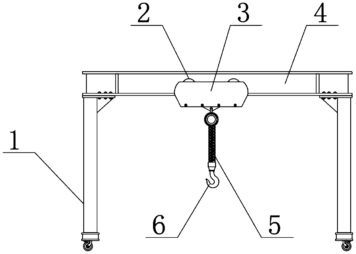
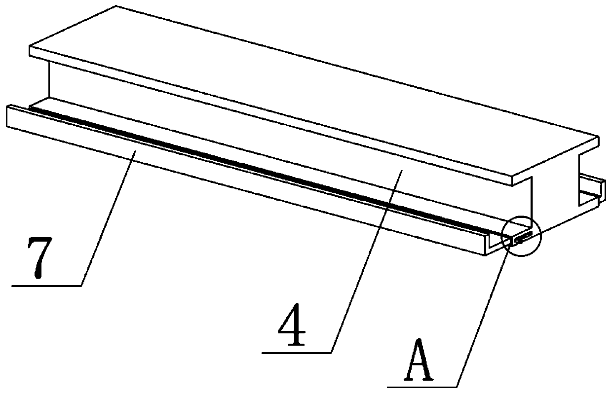
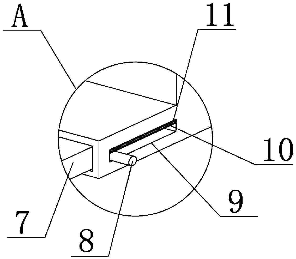
[0018] See Figure 1 to Figure 3 , The present invention provides a technical solution: a lifting device for hot-dip galvanizing production, comprising a main beam 4 with an "I"-shaped cross section, a shell 3 is provided at the bottom of the main beam 4, Rollers 2 are installed on both sides of the inner wall. Rollers 2 are inside the main beam 4. The bottom edge of the main beam 4 is convex, and the convex interior is provided with a horizontally movable limit plate 7, and the limit plate 7 The cross section is an L-shaped structure. The convex side is provided with a sliding groove 9. The inner side of the sliding groove 9 penetrates the adjusting column 8. The end of the adjusting column 8 is fixedly connected with the side of the limiting plate 7. The limiting plate 7 The inner side of the roller 2 is attached to the side of the roller 2, through the designed limit plate 7, the position of the roller 2 can be limited in use, to avoid the deviation of the ...

Example Embodiment

[0023] Example 2

[0024] The difference with this embodiment 1 is: please refer to figure 1 , figure 2 with Figure 4 , A lifting device for hot-dip galvanizing production, comprising a main beam 4 with an "I"-shaped cross section, a shell 3 is provided at the bottom of the main beam 4, and rollers 2 are installed on both sides of the inner wall of the shell 3. The roller 2 is located on the inner side of the main beam 4, the bottom edge of the main beam 4 is convex, and a horizontally movable limit plate 7 is arranged inside the convex shape. The cross section of the limit plate 7 is an L-shaped structure, convex A chute 9 is provided on the raised side. The inner side of the chute 9 penetrates the stud 12, and the end of the stud 12 is fixedly connected to the side of the limit plate 7, and the inner side of the limit plate 7 is connected to the side of the roller 2. For edge-fitting connection, the designed limit plate 7 can limit the position of the roller 2 during use to a...


PUM


Abstract

The invention discloses a lifting device for hot galvanizing production. The device comprises a main beam with the cross section which is of an H-shaped structure, the bottom of the main beam is provided with a shell, the two sides of the inner wall of the shell are provided with rollers, the rollers are located on the inner side of the main beam, the edges of the bottom of the main beam are convex, limiting plates capable of moving horizontally are arranged in the convex portions, the cross section of each limiting plate is of an L-shaped structure, and sliding grooves are formed in the sideedges of the convex shape. Through the designed limiting plates, the position of the rollers can be limited during use, and the deviation between the rollers and the side edges of the main beam is avoided, so that the use stability is ensured. Designed rubber plates are also used so that the positions of adjusting columns can be limited, and the positions are prevented from being changed after adjustment.

Description

Technical field [0001] The invention belongs to the technical field of hot-dip galvanizing production equipment, and specifically relates to a lifting device for hot-dip galvanizing production. Background technique [0002] Hot-dip galvanizing is to make the molten metal react with the iron matrix to produce an alloy layer, so that the matrix and the coating are combined. In production, the hot-dip galvanizing also needs to be sprayed, and a lifting device is needed to lift it. For later processing. [0003] The existing lifting device still has some shortcomings in use: the existing lifting device needs to be moved on the main beam by an electric hoist in order to adjust according to the position of the object. In the existing adjustment It needs to be moved by the roller, but during the movement, the outer side of the roller does not have any parts that can be restricted. Only the arch structure formed on both sides of the electric hoist is used for restriction. In long-term use...

Claims


Application Information

Patent Timeline
IPC IPC(8): B66C19/00B66C7/02B66C7/16C23C2/06
CPCB66C7/02B66C7/16B66C19/00C23C2/003C23C2/06
Inventor 许建全
Owner 鑫领域智能科技(邳州)有限公司
Why Eureka
Try Eureka