Metallurgy speed reducer

A reducer and box technology, which is applied in the direction of mechanical equipment, transmission parts, belts/chains/gears, etc., can solve the problems of increased production costs, easy splashing of lubricating oil, unfavorable streamlining of structures, etc., to reduce production and production costs Cost, prevention of spatter injection, effect of streamlining machining

Inactive Publication Date: 2020-02-07
JIANGSU TAILONG MACHINERY GRP CO CO LTD
View PDF6 Cites 0 Cited by
  • Summary
  • Abstract
  • Description
  • Claims
  • Application Information

AI Technical Summary

Problems solved by technology

[0002] Due to the high-temperature environment characteristics of the metallurgical reducer, it needs to be lubricated, ventilated, and visually monitored. When the reducer is lubricated by oil injection, the lubricating oil is ea

Method used


Image

  • Metallurgy speed reducer
  • Metallurgy speed reducer

Examples


Example Embodiment

[0010] Further description will be given below with reference to the drawings and embodiments.

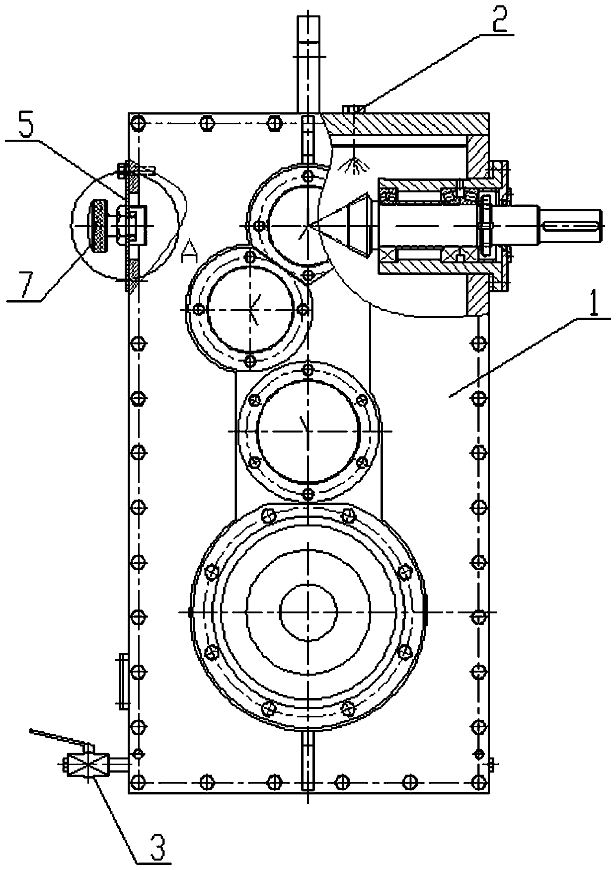
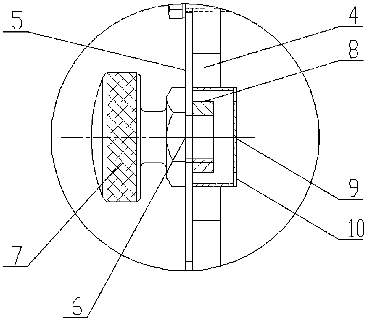
[0011] figure 1 , 2 Shown: a metallurgical reducer includes a box body 1, an oil injection hole 2, an oil discharge port 3, a sight hole cover 5, a breather cap 7, a mounting nut 8, and a shield 9. The top of the box body 1 is provided with a plurality of oil injection holes 2 corresponding to the internal transmission engagement structure for oil injection lubrication. The lower part of the side wall of the box body is provided with an oil discharge port 3, and the upper part of the side wall of the box body is provided with a viewing hole 4 and the viewing hole 4 The viewing hole cover 5 is fixedly installed by bolts. The viewing hole cover 5 is provided with a vent 6 and a mounting nut 8 is installed on the venting hole. The mounting nut 8 can be located outside or inside the viewing hole cover. This embodiment is installed inside the vent cap 7 is screwed to the mounting nut 8. Th...


PUM


Abstract

The invention relates to a metallurgy speed reducer. The metallurgy speed reducer comprises a box body, wherein the top of the box body is provided with oil spraying openings for spraying oil to the interior of the box body for lubrication, and the side wall of the lower portion of the box body is provided with an oil discharging opening; the side wall of the upper portion of the box body is provided with a sight hole, the sight hole is provided with a sight hole cover, the sight hole cover is provided with a ventilation hole, and the inner side of the sight hole cover is provided with a mounting nut corresponding to the ventilation hole, or the ventilation hole is a threaded hole; and a ventilation cap is connected with the ventilation hole in a screwed mode through the mounting nut or threaded hole structure, a block cover for covering the mounting nut or the ventilation hole is arranged on the inner side of the sight hole cover, and small holes are formed in the block cover. The metallurgy speed reducer is simple in structure, and the ventilation cap and the sight hole are combined, so that the ventilation cap is effectively prevented from sputtering and spraying the oil.

Description

technical field [0001] The invention relates to a reducer, in particular to a reducer for metallurgy. Background technique [0002] Due to the high-temperature environment characteristics of the metallurgical reducer, it needs to be lubricated, ventilated, and visually monitored. When the reducer is lubricated by oil injection, the lubricating oil is easy to splash out from the breathable cap, which affects the use environment. Configuring a breathable cap and a viewing hole structure is not conducive to simplifying the structure and increasing production costs. Contents of the invention [0003] The invention provides a metallurgical reducer with simple structure, which combines a vent cap and a visible hole to effectively prevent sputtering and oil injection from the vent cap. [0004] The technical scheme adopted in the present invention is: a reducer for metallurgy, including a box body, the top of the box body is provided with an oil injection port for spraying oil t...

Claims


Application Information

Patent Timeline
IPC IPC(8): F16H57/027F16H57/04
CPCF16H57/027F16H57/04
Inventor 胡美娟陈新志李素珍叶青刘涵波刘燕汪亚玲
Owner JIANGSU TAILONG MACHINERY GRP CO CO LTD
Why Eureka
Try Eureka